EasyManuals Logo

Omron MX2 Series User Manual

Omron MX2 Series
612 pages
To Next Page IconTo Next Page
To Previous Page IconTo Previous Page
Page #487 background imageLoading...
Page #487 background image
8 Communications Functions
8 - 43
Multi-function Compact Inverter 3G3MX2-EV2 User’s Manual (I666-E1)
Register
No.
Modbus
register
spec.
No
Function name
Parameter No.
R/W
Monitor or setting
data
Data
resolution
0026
hex
0025 hex
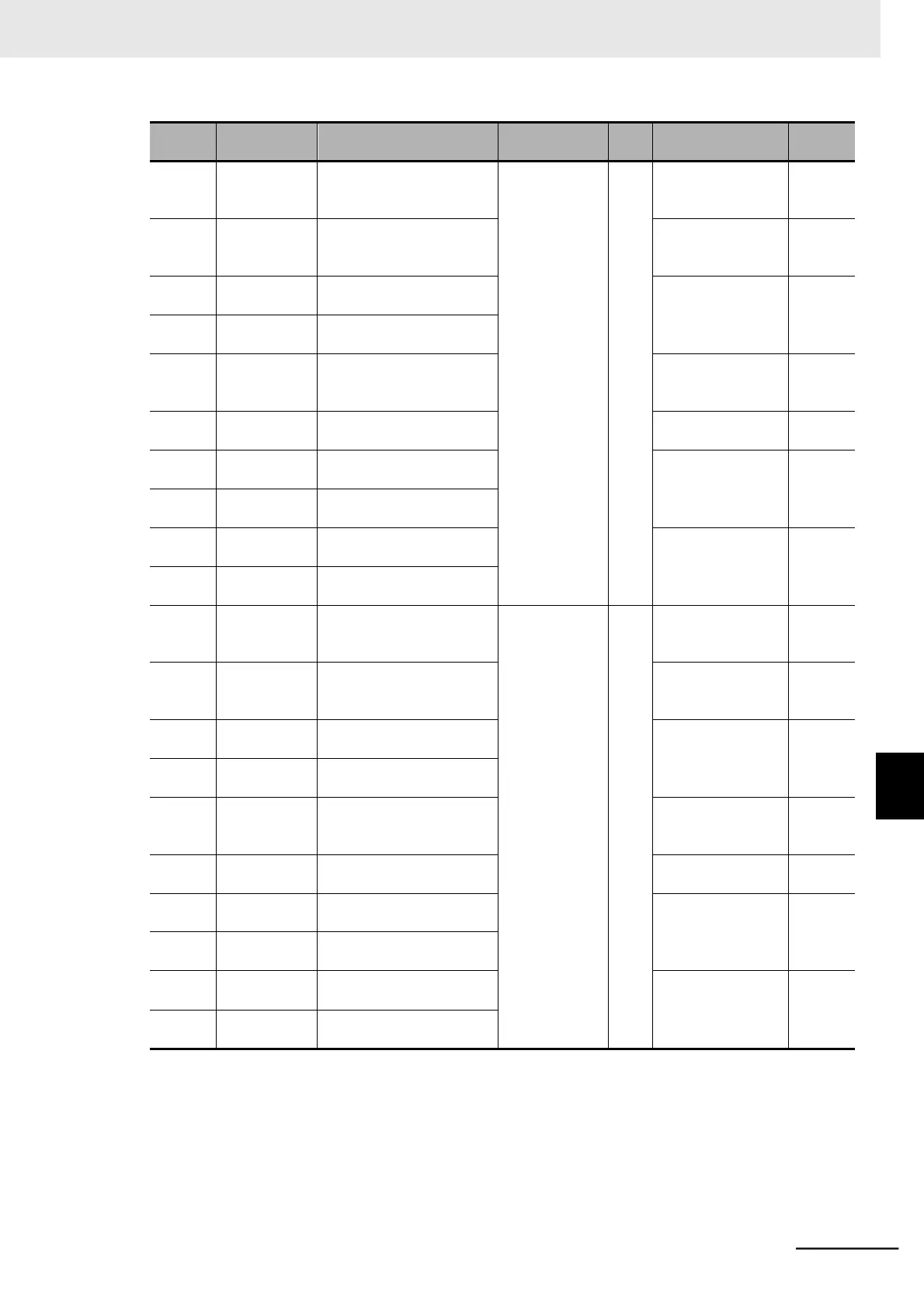
Fault Monitor 3 Fault
Factor
d083
R
Refer to Inverter trip
fault factor list on
page 8-46.
0027
hex
0026 hex
Fault Monitor 3 Inverter
Status
Refer to Inverter trip
fault factor list on
page 8-46.
0028
hex
0027 hex
Fault Monitor 3 Frequency
(HIGH)
0 to 59000
0.01
[Hz]
0029
hex
0028 hex
Fault Monitor 3 Frequency
(LOW)
002A
hex
0029 hex
Fault Monitor 3 Output
Current
Output current
value at the time of
trip
0.01 [A]
002B
hex
002A hex
Fault Monitor 3 Main circuit
DC voltage
DC input voltage at
the time of trip
0.1 [V]
002C
hex
002B hex
Fault Monitor 3 Total RUN
Time (HIGH)
Total RUN time
before the trip
1 [h]
002D
hex
002C hex
Fault Monitor 3 Total RUN
Time (LOW)
002E
hex
002D hex
Fault Monitor 3 Total
Power ON Time (HIGH)
Total power ON
time before the trip
1 [h]
002F
hex
002E hex
Fault Monitor 3 Total
Power ON Time (LOW)
0030
hex
002F hex
Fault Monitor 4 Fault
Factor
d084
R
Refer to Inverter trip
fault factor list on
page 8-46.
0031
hex
0030 hex
Fault Monitor 4 Inverter
Status
Refer to Inverter trip
fault factor list on
page 8-46.
0032
hex
0031 hex
Fault Monitor 4 Frequency
(HIGH)
0 to 59000
0.01
[Hz]
0033
hex
0032 hex
Fault Monitor 4 Frequency
(LOW)
0034
hex
0033 hex
Fault Monitor 4 Output
Current
Output current
value at the time of
trip
0.01 [A]
0035
hex
0034 hex
Fault Monitor 4 Main circuit
DC voltage
DC input voltage at
the time of trip
0.1 [V]
0036
hex
0035 hex
Fault Monitor 4 Total RUN
Time (HIGH)
Total RUN time
before the trip
1 [h]
0037
hex
0036 hex
Fault Monitor 4 Total RUN
Time (LOW)
0038
hex
0037 hex
Fault Monitor 4 Total
Power ON Time (HIGH)
Total power ON
time before the trip
1 [h]
0039
hex
0038 hex
Fault Monitor 4 Total
Power ON Time (LOW)
8
8-9 Modbus Communication Data Lists
8-9-2 Monitor Function/Enter Command Regis-
ter List

Table of Contents

Questions and Answers:

Question and Answer IconNeed help?

Do you have a question about the Omron MX2 Series and is the answer not in the manual?

Omron MX2 Series Specifications

General IconGeneral
Cooling MethodFan cooling
Output Frequency Range0.1 to 400 Hz
Control MethodV/f control, Sensorless vector control
Protection FunctionsOvercurrent, overvoltage, undervoltage, overload, overheating, short circuit
Communication OptionsModbus RTU
Overload Capacity150% for 60 seconds
Braking UnitBuilt-in
Ambient Operating Temperature-10°C to +50°C
EnclosureIP20
Storage Temperature-20°C to +65°C
Humidity5 to 95% RH (non-condensing)
AltitudeUp to 1000m
Power Supply Voltage200-240V AC
Input Voltage3-phase 200-240V AC

Related product manuals