336
Example Calculations Calculations
would be as shown below for an input ON delay of
1.5 ms, an out
-
put ON delay of 15 ms, and a cycle time of 20 ms.
Minimum I/O Response Time
Time = 1.5 ms + (20 ms x 3) + 15 ms = 76.5 ms
Maximum I/O Response Time
Time = 1.5 ms + (20 ms x 4) + 15 ms = 96.5 ms
Note 1. The
cycle time may be less than or equal to the remote I/O transmission time
when there are Special I/O Units on Slave Racks. If this is the case, there
may be cycles when I/O is not refreshed between the Master and the
C200HS
CPU.
2. Refreshing
is performed for
Masters only once per cycle, and then only after
confirming completion of the remote cycle.
3. The
short duration of ON/OFF status produced by dif
ferentiated instructions
can cause inaccurate signals when dealing with Remote I/O Systems un-
less appropriate programming steps are taken.
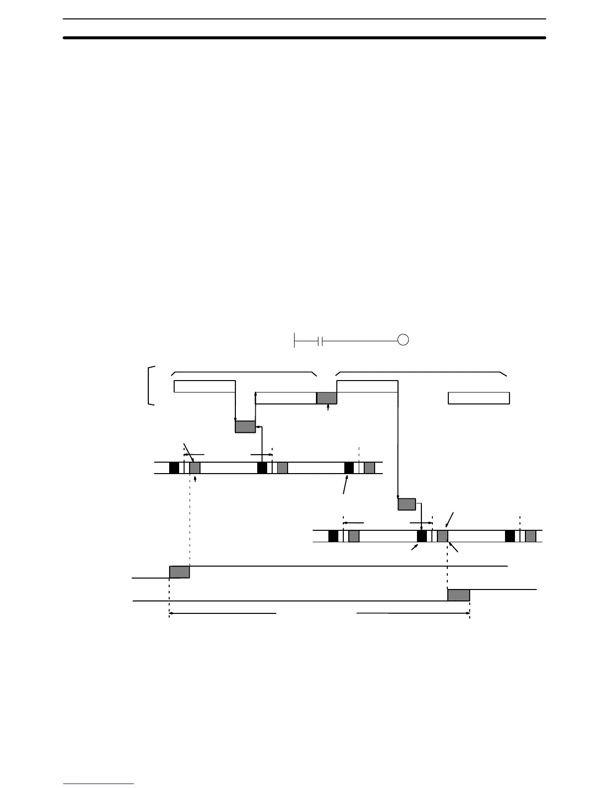
6-4-3 Host Link Systems
The
following diagram illustrates the processing that takes place when an input
on
one PC is transferred through the
Host Link System to turn ON an output on
another PC. Refer to Host Link System documentation for further details.
X
Input
on #0
Output on #32
Cycle time
Input
signal
Output
signal
I/O refresh
I/O refresh
I/O response time
CPU reads
input signal
CPU writes
output signal
Output ON delay
Input ON delay
Host link service
Buf
fer for Host
Link Unit # 0
Cycle time
Buf
fer for Host
Link Unit # 31
PC for Host
Link Unit # 31
PC for Host
Link Unit # 0
Host computer
Host computer
processing time
Command Command
Response Response
Command/response for Unit # 0
Command/response for Unit # 31
Host link service
The
equations used to calculate the minimum and maximum cycle times are giv
-
en
below
. The number of cycles required for
each PC depends on the amount of
data being read/written.
Minimum
response time =
Input ON delay + Command transmission time + (Cycle time of PC for Unit #0 x 3) + Response transmis
-
sion time + Host computer processing time + Command transmission time + (Cycle time of PC for Unit #31
x 3) + Output ON delay
Maximum response time =
Input ON delay + Command transmission time + (Cycle time of PC for Unit #0 x 10) + Response transmis
-
sion time + Host computer processing time + Command transmission time + (Cycle time of PC for Unit #31
x 10) + Output ON delay
I/O Response Time Section 6-4