338
Inserting the following values into this equation produces a minimum I/O re-
sponse time of 149.3 ms.
Input ON delay: 1.5 ms
Output ON delay: 15 ms
Cycle time for PC of Unit 0: 20 ms
Cycle time for PC of Unit 7: 50 ms
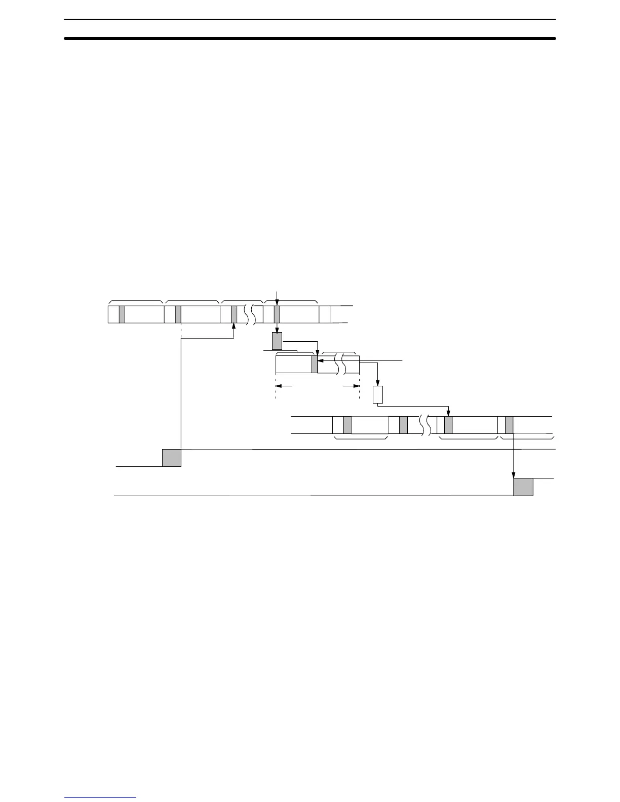
The following diagram illustrates the data flow that will produce the maximum
response
time. Delays occur because signals or data is received just after they
would
be processed or because data is sent during processing. In either case,
processing must wait until the next scan/polling cycle.
First
output
to the buf
fer in the polling unit is delayed by the setting of the number
of LR bits to be refreshed each scan. A similar delay is present when the LR data
reaches
Unit 7. The polling delay is the result
of the LR data in its PC being up
-
dated immediately after
the
previous was sent to the buf
fer in the PC Link Unit,
cause
a delay until the next polling cycle. One more polling cycle is then required
before the data reaches the buffer in PC Link Unit 7.
PC
with
Unit 0
Buf
fer in Unit 0
PC Link Unit
transmissions
Buf
fer in Unit 7
PC with
Unit 7
Input
Output
PC Link
polling time
Cycle time
Cycle time
I/O refresh
Induction sequence
processing time
Maximum
transmission
time
Polling delay
The equation for maximum I/O response time is thus as follows:
Response
time = Input ON delay + [Cycle time of PC
of Unit 0 x (Number of LR
transfer
bits
÷
I/O refresh bits)] +
α
+ (PC Link polling time +
Induction sequence processing time) + {Cycle time of PC of
Unit
7 x [(Number of LR transfer bits
÷
I/O refresh bits) x 2 + 1]}
+ β + Output ON delay
If
cycle time of
PC of Unit 0 > PC Link polling time,
α
= cycle time of PC of Unit 0. If
cycle time of PC of Unit 0 < PC Link polling time, α = PC Link polling time.
If
cycle time of PC of Unit 7 > PC Link polling time,
β
= cycle time of PC of Unit 7. If
cycle time of PC of Unit 7 < PC Link polling time, β = PC Link polling time.
Inserting the following values into this equation produces a maximum I/O re-
sponse time of 661.3 ms.
Input ON delay: 1.5 ms
Output ON delay: 15 ms
Cycle time for PC of Unit 0: 20 ms
Cycle time for PC of Unit 7: 50 ms
PC Link polling time: 2.8 ms x 8 PCs + 10 ms = 32.4 ms
Maximum Response Time
I/O Response Time Section 6-4