383
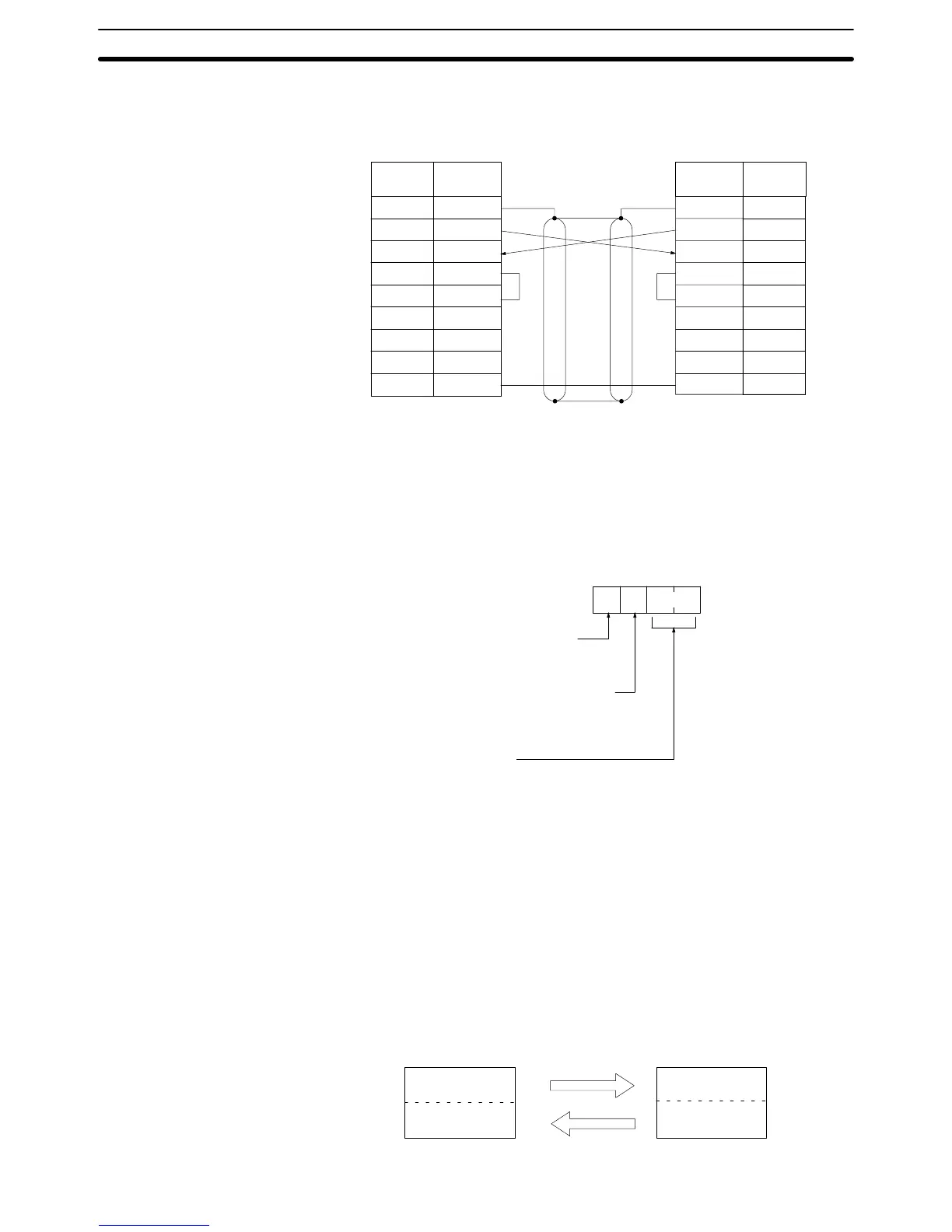
Plug: XM2A-0901 (OMRON) or equivalent
Hood: XM2S-0901 (OMRON) or equivalent
1
2
3
4
5
6
FG
SD
RD
RS
CS
–
–
–
SG
7
8
9
1
2
3
4
5
6
7
8
9
FG
SD
RD
RS
CS
–
–
SG9
C200HS C200HS
Signal
Abb.
Pin
No.
Signal
Abb.
Pin
No.
–
Note Ground the FG terminals the C200HS to a resistance of 100 Ω or less.
PC Setup To
use a 1:1 link,
the only settings necessary are the communications mode and
the
link words. Set the communications mode for one of the PCs to the 1:1 mas
-
ter and the other to the 1:1 slave, and then set the link words in the PC desig-
nated
as the master
. Bits 08 to 1
1 are valid only for the master for link one-to-one.
Communications
mode
2: One-to-one link slave
3: One-to-one link master
15 0
Bit
DM 6645:
RS-232C port
Link
words for one-to-one link
0:
LR 00 to LR 63
1: LR 00 to LR 31
2: LR 00 to LR 16
Port settings
00: Standard communication parameters
Communications Procedure If
the settings for the master and the slave are made correctly
, then the
one-to-
one
link will be automatically started up simply by turning on the
power supply to
both
the C200HSs and operation will be independent of the C200HS operating
modes.
Application Example This
example shows a program for verifying the conditions for executing a one-
to-one
link using the RS-232C ports. Before executing the program, set the fol
-
lowing PC Setup parameters.
Master: DM 6645: 3200 (one-to-one link master; Area used: LR 00 to LR 15)
Slave: DM 6645: 2000 (one-to-one link slave)
The
defaults are assumed for all
other PC Setup parameters. The words used
for the one-to-one link are as shown below.
LR00
LR07
LR08
LR15
LR00
LR07
LR08
LR15
Master
Area
for writing
Area
for reading
Slave
Area
for writing
Area for reading
Parameters for Host Link and RS-232C Communications
Section 8-2