EasyManua.ls Logo

Omron SYSMAC C200HS User Manual

Omron SYSMAC C200HS
503 pages
To Next Page IconTo Next Page
To Previous Page IconTo Previous Page
Page #411 background imageLoading...
Page #411 background image
406
time
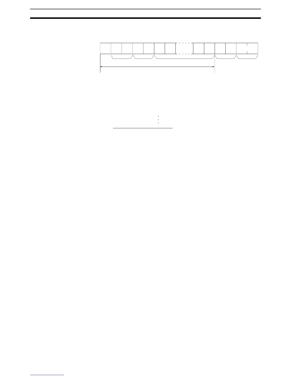
a frame is received and checking the result against the FCS that is included
in the frame makes it possible to check for data errors in the frame.
FCS
:
01RR0@00142
Text
Node
no.
Header
code
FCS
calculation range
Terminator
@ 40 0100 0000
EOR
1 31 0011 0001
EOR
0 30 0011 0000
EOR
R 52 0101 0010
1 31 0011 0001
0100 0010
↓↓
Converted to hexadecimal.
42
Handled as ASCII characters.
ASCII code
Calculation
result
Example Program for FCS This
example shows a BASIC subroutine program for executing an FCS check
on a frame received by the host computer.
400 *FCSCHECK
410 L=LEN(RESPONSE$) ’ Data transmitted and received.
. . . . . . . . . .
420 Q=0:FCSCK$=“ ”
430 A$=RIGHT$(RESPONSE$,1)
440 PRINT RESPONSE$,AS,L
450 IF A$=”*” THEN LENGS=LEN(RESPONSE$)-3
ELSE LENGS=LEN(RESPONSE$)-2
460 FCSP$=MID$(RESPONSE$,LENGS+1,2) ’ FCS data received.
. . .
470 FOR I=1 TO LENGS ’ Number of characters in FCS.
. . . . . . . . . .
480 Q=ASC(MID$(RESPONSE$,I,1)) XOR Q
490 NEXT I
500 FCSD$=HEX$(Q)
510 IF LEN(FCSD$)=1 THEN FCSD$=”0”+FCSD$ ’FCS result
520 IF FCSD$<>FCSP$ THEN FCSCK$=”ERR”
530 PRINT“FCSD$=”;FCSD$,“FCSP$=”;FCSP$,“FCSCK$=”;FCSCK$
540 RETURN
Note 1. Normal
reception data includes the FCS, delimiter or terminator
, and so on.
When
an error occurs in transmission, however the FCS or some other data
may not be
included. Be sure to program the system to cover this possibility
.
2. In this program example, the CR code (CHR$(13)) is not entered for RE-
SPONSE$. When including the CR code, make the changes in lines 430
and 450.
11-2-2 Commands from the PC
In
host link communications, commands are ordinarily sent from
the host com
-
puter
to the PC, but it is also possible for commands to be sent from the PC to the
host
computer
. In Host Link Mode,
any data can be transmitted from the PC to
the
host computer
. T
o send a command to the host computer
, use the TRANS
-
MIT instruction (TXD(--)) in the PC program in Host Link Mode.
TXD(––)
outputs data from the specified port (the RS-232C port or the peripher
-
al port). Refer to page 299 for details on using TXD(––).
Command and Response Formats
Section 11-2

Table of Contents

Other manuals for Omron SYSMAC C200HS

Questions and Answers:

Omron SYSMAC C200HS Specifications

General IconGeneral
ModelC200HS
ManufacturerOmron
SeriesSYSMAC
Humidity10 to 90% RH (non-condensing)
Programming LanguageLadder logic
Program MemoryRAM/EPROM/EEPROM
Communication ProtocolsSYSMAC LINK, SYSMAC NET
Communication PortsRS-232C, RS-422
Power Supply100-240V AC, 24V DC
Operating Temperature0 to 55°C
Vibration Resistance10 to 57 Hz, 0.075mm amplitude

Summary

SECTION 1 Introduction

1-1 Overview

Provides a general introduction to Programmable Controllers (PCs), their operation, and programming concepts.

SECTION 2 Hardware Considerations

2-1 CPU Components

Details the main components of the C200HS CPU, including indicators, fuses, and connection ports.

SECTION 3 Memory Areas

SECTION 4 Writing and Inputting the Program

4-4 Basic Ladder Diagrams

Introduces fundamental concepts of ladder diagram programming, including rungs, conditions, and instructions.

4-7 Inputting, Modifying, and Checking the Program

Details the procedures for entering, editing, checking, and debugging programs using the Programming Console.

SECTION 5 Instruction Set

5-8 Ladder Diagram Instructions

Details fundamental instructions used in ladder diagrams like LOAD, AND, OR, and their variations.

SECTION 6 Program Execution Timing

6-4 I/O Response Time

Details the time taken for the PC to respond to input signals and produce output signals.

SECTION 7 Program Monitoring and Execution

7-1 Monitoring Operation and Modifying Data

Covers procedures for observing and modifying PC data like bits, words, timers, and counters.

SECTION 8 Communications

8-2 Parameters for Host Link and RS-232C Communications

Details essential PC Setup parameters required for enabling Host Link and RS-232C communications.

SECTION 10 Troubleshooting

10-4 Error Messages

Lists common error messages, their probable causes, and possible corrections for diagnosing system problems.

SECTION 11 Host Link Commands

11-3 Host Link Commands

Details the various commands used for host computer communication with the C200HS PC.

Appendix B Programming Instructions

Appendix D Memory Areas

Appendix E PC Setup

RS-232C Port Settings (DM 6645 to DM 6649)

Details the specific parameters for configuring the RS-232C port, essential for communication setup.

Related product manuals