EasyManua.ls Logo

Omron SYSMAC C200HS User Manual

Omron SYSMAC C200HS
503 pages
To Next Page IconTo Next Page
To Previous Page IconTo Previous Page
Page #412 background imageLoading...
Page #412 background image
407
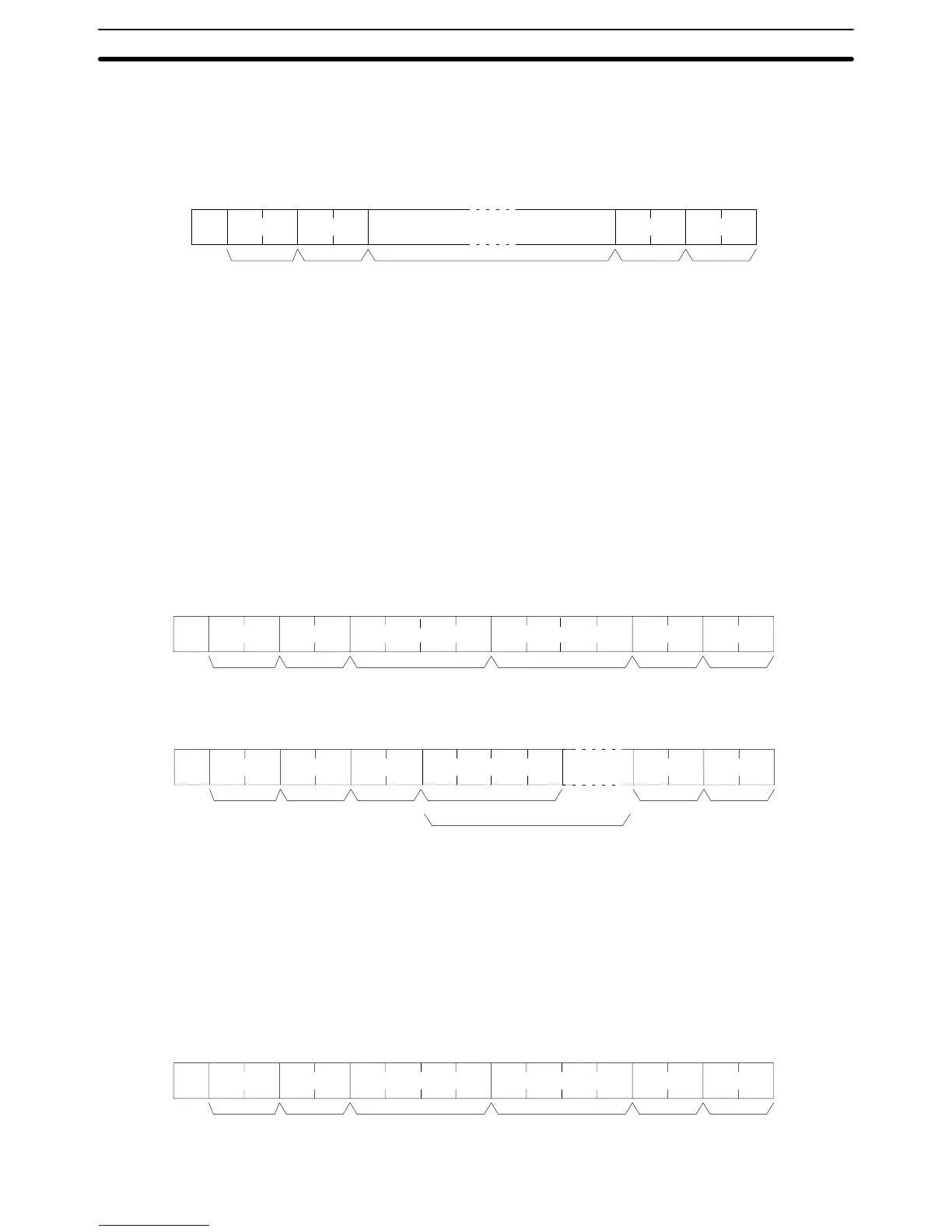
Reception Format When
TXD(––) is executed, the data stored in the words beginning with the first
send
word is converted to ASCII and
output to the host computer as a host link
command in the format shown below. The “@” symbol, node number, header
code,
FCS, and delimiter are
all added automatically when the transmission is
sent.
At the host computer
, it is necessary to prepare
in advance a program for
interpreting and processing this format.
@
:
EX
FCS
Node
no.
Header
code
(Must
be “EX”)
Text
122 characters max.
Terminator
One byte of data (2 digits hexadecimal) is
converted
to two characters in ASCII
for
transmission, the amount of data in the transmission is twice the amount of
words
specified for TXD(––). The maximum number of characters for transmis
-
sion is 122 and the maximum number of bytes that can be designated for
TXD(––) is one half of that, or 61.
11-3 Host Link Commands
This
section explains the commands that can be issued from the host
computer
to the PC.
11-3-1 IR/SR AREA READ –– RR
Reads
the contents of the specified number
of IR and SR words, starting from
the specified word.
Command Format
@
FCS
x
10
1
x 10
0
x 10
3
x 10
2
:
RR
x 10
1
x 10
0
x 10
3
x 10
2
x 10
1
x 10
0
Node
no.
Header
code
Beginning
word
(0000 to 051
1)
No. of words
(0000 to 0512)
Terminator
Response Format
@ RR
FCS
x
10
1
x 10
0
x 16
1
x 16
0
:
x 16
3
x 16
2
x 16
1
x 16
0
End code
Read
data (1 word)
Read
data (for number of words read)
TerminatorNode
no.
Header
code
Parameters Read Data (Response)
The
contents of the number of words specified by the command are returned in
hexadecimal as a response. The words are returned in order, starting with the
specified beginning word.
11-3-2 LR AREA READ –– RL
Reads
the contents of the specified number of LR words, starting from the speci
-
fied word.
Command Format
@ RL
FCS
x
10
1
x 10
0
x 10
3
x 10
2
:
x 10
1
x 10
0
x 10
3
x 10
2
x 10
1
x 10
0
Node no.
Header
code
Beginning word
(0000 to 0063)
No. of words
(0001 to 0064)
Terminator
Host Link Commands
Section 11-3

Table of Contents

Other manuals for Omron SYSMAC C200HS

Questions and Answers:

Omron SYSMAC C200HS Specifications

General IconGeneral
ModelC200HS
ManufacturerOmron
SeriesSYSMAC
Humidity10 to 90% RH (non-condensing)
Programming LanguageLadder logic
Program MemoryRAM/EPROM/EEPROM
Communication ProtocolsSYSMAC LINK, SYSMAC NET
Communication PortsRS-232C, RS-422
Power Supply100-240V AC, 24V DC
Operating Temperature0 to 55°C
Vibration Resistance10 to 57 Hz, 0.075mm amplitude

Summary

SECTION 1 Introduction

1-1 Overview

Provides a general introduction to Programmable Controllers (PCs), their operation, and programming concepts.

SECTION 2 Hardware Considerations

2-1 CPU Components

Details the main components of the C200HS CPU, including indicators, fuses, and connection ports.

SECTION 3 Memory Areas

SECTION 4 Writing and Inputting the Program

4-4 Basic Ladder Diagrams

Introduces fundamental concepts of ladder diagram programming, including rungs, conditions, and instructions.

4-7 Inputting, Modifying, and Checking the Program

Details the procedures for entering, editing, checking, and debugging programs using the Programming Console.

SECTION 5 Instruction Set

5-8 Ladder Diagram Instructions

Details fundamental instructions used in ladder diagrams like LOAD, AND, OR, and their variations.

SECTION 6 Program Execution Timing

6-4 I/O Response Time

Details the time taken for the PC to respond to input signals and produce output signals.

SECTION 7 Program Monitoring and Execution

7-1 Monitoring Operation and Modifying Data

Covers procedures for observing and modifying PC data like bits, words, timers, and counters.

SECTION 8 Communications

8-2 Parameters for Host Link and RS-232C Communications

Details essential PC Setup parameters required for enabling Host Link and RS-232C communications.

SECTION 10 Troubleshooting

10-4 Error Messages

Lists common error messages, their probable causes, and possible corrections for diagnosing system problems.

SECTION 11 Host Link Commands

11-3 Host Link Commands

Details the various commands used for host computer communication with the C200HS PC.

Appendix B Programming Instructions

Appendix D Memory Areas

Appendix E PC Setup

RS-232C Port Settings (DM 6645 to DM 6649)

Details the specific parameters for configuring the RS-232C port, essential for communication setup.

Related product manuals