Scan Tool User Guide 13
2: Setup
Provide Power to Scan Tool
Before using the scan tool, you must provide power
to the scan tool. There are three methods for provid-
ing power to the scan tool:
• AC/DC external power adapter
• Cable connection to vehicle
• Internal battery pack
During vehicle testing, power for the scan tool is
usually provided through the vehicle cable connec-
tion. (Therefore, it is not necessary to have the
internal battery pack fully charged before testing.)
When the scan tool is not connected to a vehicle, the
scan tool can be powered with an AC/DC external
power adapter (OTC P/N 3421-04) or the internal
rechargeable battery pack (OTC P/N 239180).
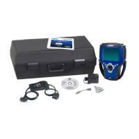
Figure 2.1: Power Adapter and Scan Tool Power Port
Battery Fast Charge
The Scan Tool battery fast charge recharges the 9.6
volt Nickel Metal Hydrate (NiMH) battery in 3 hours.
1 Plug the 12-volt Battery Charger into a 120-volt wall
outlet.
2 Plug the Battery Charger connector into the External
Power Port located on the top of the Scan Tool, see
Figure 2.1
. The battery is fully charged in 3 hours.
IMPORTANT: For maximum battery life, do not leave
the charger connected more than 12 hours.
Connect the Hardware Module
(optional)
If using the InfoTech/Scope, or Gas M-P software
applications, you must first connect the hardware
module to the scan tool. Use the following steps to
connect a hardware module.
IMPORTANT: Turn off scan tool before connecting
or removing hardware module. Failure to do so may
cause internal damage not covered by warranty.
1 Press the tool On/Off button to turn the power off.
2 Position the scan tool to access the back side, then
open the protective HIP door.
3 Slide the locking bars out on the hardware module
(you may need to hold them out).
4 Position the hardware module with the hardware
interface ports aligned.
5 Place the module into the compartment and press it
into place.
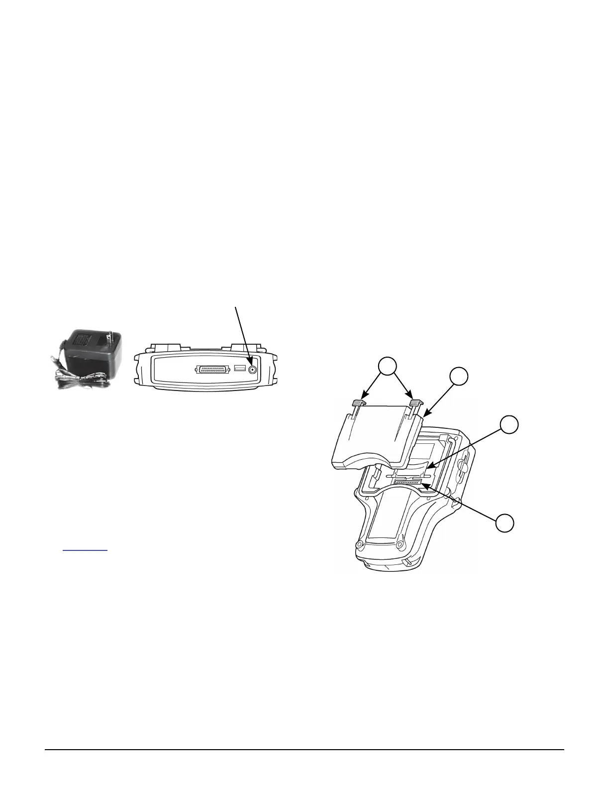
Item 1 Locking Bars
Item 2 Hardware Module
Item 3 Hardware Interface Port Door (shown open)
Item 4 Hardware Interface Port
Figure 2.2: Hardware Module Connection
6 Slide the locking bars in to lock the module in place.
NOTE: To remove the module, slide the locking bars out
and pull the module upward. Close the HIP door.