20 Scan Tool User Guide
Test Startup and Vehicle Connection
3: Scan Diagnostics Applications
Step 4: Select the Diagnostic Function
After you connect the cable and press the ENTER
key on the scan tool, use the following steps if either
a Message screen or a Diagnostic Menu screen
appears. For OBD II vehicles, use the following steps
after you have viewed the Quick Test results screen
and pressed the ENTER key.
1 One or more instruction screens may appear. If so,
read each screen, follow the instructions, and press
the OK function key to display the next screen. Do this
until the Diagnostic Menu screen appears.
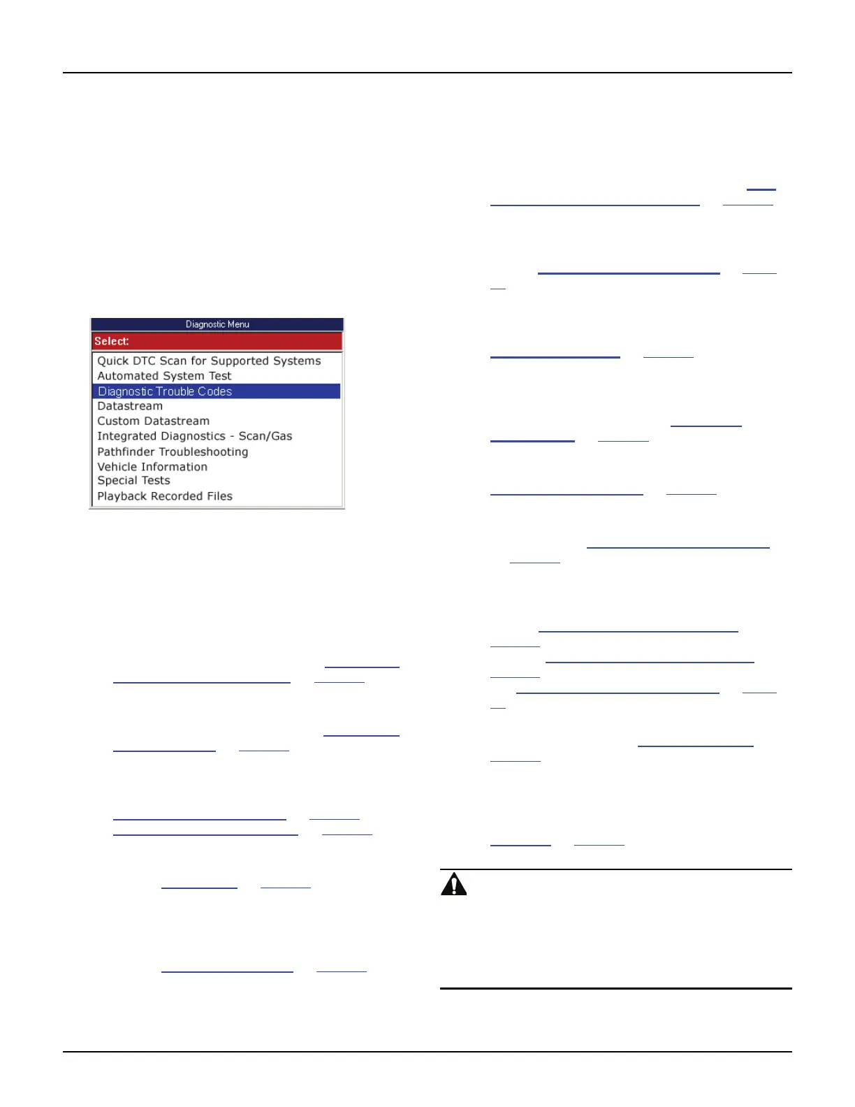
Figure 3.14: Diagnostic Menu Screen
NOTE: During testing, the Diagnostic Menu displays only
the options available for the vehicle being tested.
2 Select the option for the diagnostic function to
perform and press the ENTER key:
• Quick DTC Scan for Supported Systems to
quickly check all available ECUs for diagnostic
trouble codes. For details, refer to Quick DTC
Scan (Supported Systems) on page 21.
• Automated System Test
TM
to quickly check all
available ECUs for vital data and diagnostic
trouble codes. For details, refer to Automated
System TestTM on page 23.
• Diagnostic Trouble Codes (Modes 2,3,4 and
7) to view and clear diagnostic trouble codes
set by the vehicle ECU(s). For details, refer to
Diagnostic Trouble Codes
on page 27 and
Freeze Frame Data (Mode 2)
on page 25
• Datastream (Mode 1) to view sensor and
switch datastream information. For details,
refer to Datastream
on page 39.
• Custom Datastream to view live data readings
for specific sensors and switches and to
increase the refresh rate by viewing fewer
items than normal Datastream. For details,
refer to Custom Datastream
on page 51.
• Integrated Diagnostics Scan / Gas to view
exhaust gas readings (CO, CO2, HC, O2,
NOX, AFR) along with the sensor and switch
datastream readings. For details, refer to Inte-
grated Diagnostics - Scan / Gas on page 53.
• Pathfinder Troubleshooting to view vehicle-
specific information, such as DTC descriptions,
TSBs, component locations, etc. For details,
refer to Pathfinder Troubleshooting
on page
55.
• Vehicle Information to view vehicle-specific
information, such as TSBs, specifications,
component locations, etc. For details, refer to
Vehicle Information
on page 63.
• PROM ID (may be Module Info or Controller ID)
to view the ID number for the selected
computer’s programmable read-only memory
(PROM). For details, refer to PROM ID /
Controller ID on page 65.
• Diagnostic States (GM) to place a vehicle in
special test modes (states). For details, refer to
Diagnostic States (GM)
on page 67.
• Post Collision Tests (Air Bag) to view instruc-
tions for testing air bags after repair(s). For
details, refer to Post Collision Test (Airbag)
on page 69
.
• Special Tests (Modes 1,5,6,8 and 7) to
perform special diagnostic tests by manually
controlling system components. For details,
refer to Special Tests (Actuator Tests)
on
page 71
, to view failed OBD II component tests
also see Non-Continuous Tests (Mode 6)
on
page 26
and to view Oxygen Sensor tests also
see Oxygen Sensor Tests (Mode 5)
on page
26 .
• Readiness Status to review OBD II System
readiness. Also refer to Readiness Status
on
page 26
.
• Playback Recorded Files to view data
recorded with the Automated System Test,
Datastream Record function and the DTC-Trig-
gered Recording function. For details, refer to
Playback
on page 75.
WARNING: Before performing any diagnostic
functions, refer to the Safety Precautions and instruc-
tions provided in this User Guide and the warnings
provided by the vehicle manufacturer. In addition,
follow any warnings and descriptions provided on the
scan tool screens.