If the compatible mode setting is set to “FP-X mode”, "Table setting mode" cannot be selected.
1.1.2 Unit type and available functions
Available conditions vary by functions.
■
Comparison of functions and performances
Item
Transistor output type Relay output type
C14T C30T C60T C14R C30R C60R
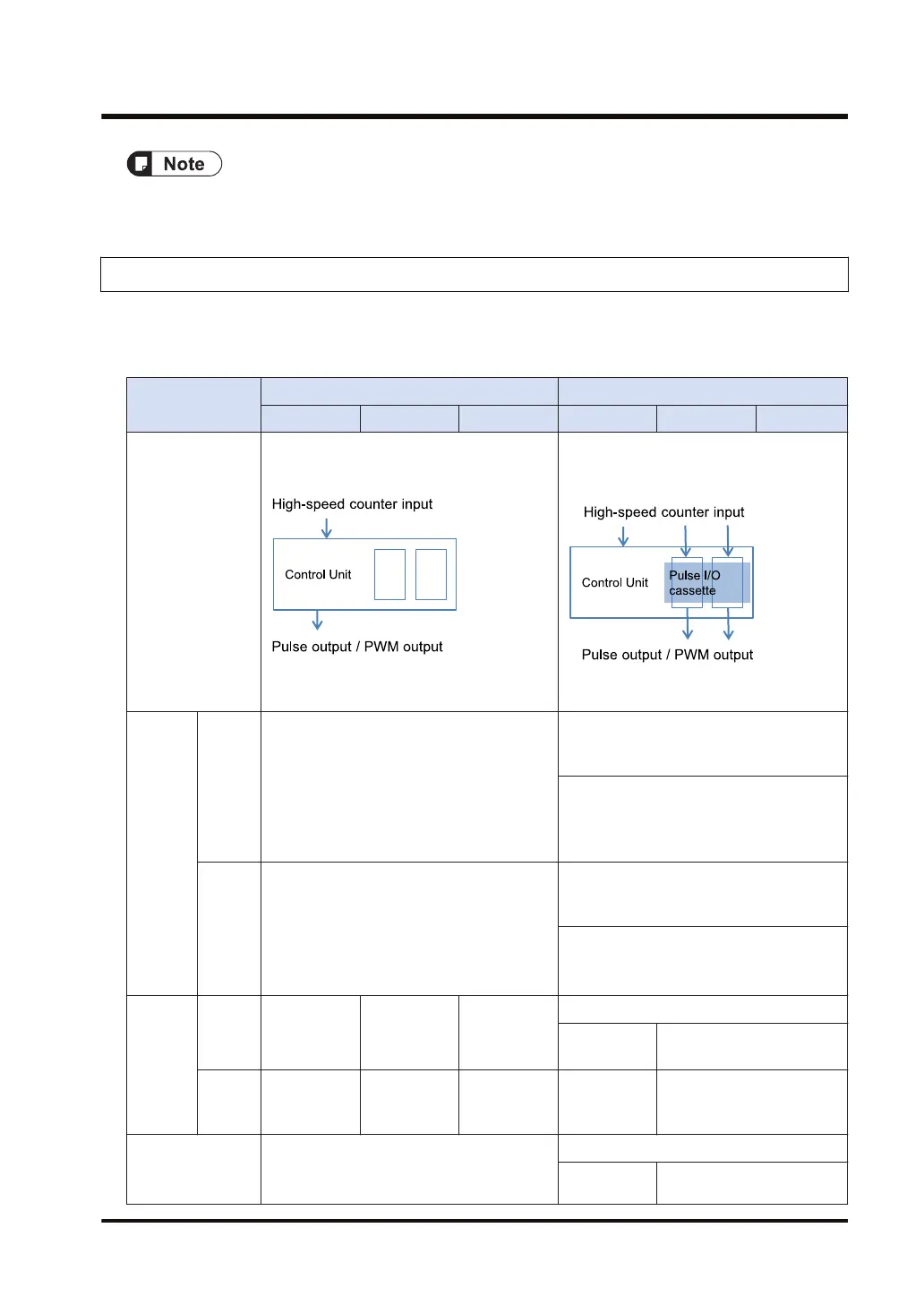
Configuration
Using the input section of the Control Unit
Using the output section of the Control Unit
Using the input section of the Control Unit
or the input section of the pulse I/O
cassette
Using the output section of the pulse I/O
cassette
High-
speed
counter
Single-
phase
Max. 8 channels (CH0 to CH7)
Max. 100 kHz × 4 + Max. 10 kHz × 4
Using the input of the Control Unit
Max. 8 channels (CH0 to CH7), Max. 10
kHz × 8
Per one pulse I/O cassette
Max. 2 channels (CH8 and CH9 or CHA
and CHB)
Max. 100 kHz × 2
2-phase
Max. 4 channels (CH0, CH2, CH4, and CH6)
Max. 50 kHz × 2 + Max. 10 kHz × 2
Using the input of the Control Unit
Max. 4 channels (CH0, CH2, CH4, and
CH6), Max. 5 kHz × 4
Per one pulse I/O cassette
Max. 1 channel (CH8 or CHA)
Max. 50 kHz×2
Pulse
Output
Indepen
dent
Max. 3 axes
(CH0 to CH2)
Max. 4 axes
(CH0 to CH3)
Max. 6 axes
(CH0 to CH5)
Per one pulse I/O cassette: Max. 1 axis
Max. 1 axis
(CH0)
Max. 2 axes (CH0 and
CH1)
(Note 3)
Interpol
ation
Max. 2 axes
(CH0)
Max. 4 axes
(CH0 and
CH2)
Max. 6 axes
(CH0, CH2,
and CH4)
Not available
Max. 2 axes (CH0)
(Note 3)
PWM output Max. 4 points (CH0 to CH3)
Per one pulse I/O cassette: Max. 1 point
Max. 1 point
Max. 2 points (CH0 and
CH1)
(Note 3)
1.1 Functions of Unit
WUME-FPXHPOSG-01 1-3

 Loading...


