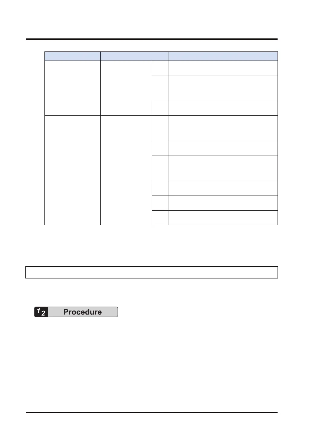
Classification No. and setting item Settings
CH1
Select either Addition input (X1) or Subtraction
input (X1).
CH2
Select either Addition input (X2), Subtraction
input (X2), 2-phase input (X2, X3), Individual
input (X2, X3), or Direction distinction input (X2,
X3).
CH3
Select either Addition input (X3) or Subtraction
input (X3).
Control Unit input
settings 2
(HSC / PLS)
401
High-speed counter
pulse output setting
(X4 to X7)
CH4
Select either Addition input (X4), Subtraction
input (X4), 2-phase input (X4, X5), Individual
input (X4, X5), or Direction distinction input (X4,
X5).
CH5
Select either Addition input (X5) or Subtraction
input (X5).
CH6
Select either Addition input (X6), Subtraction
input (X6), 2-phase input (X6, X7), Individual
input (X6, X7), or Direction distinction input (X6,
X7).
X6
To use the external reset input, select the reset
input of high-speed counter CH0.
CH7
Select either Addition input (X7) or Subtraction
input (X7).
X7
To use the external reset input, select the reset
input of high-speed counter CH2.
(Note 1) Displayed items and ranges vary depending on models of the Control Unit.
(Note 2) Select "Not set XX as High Speed Counter" for the input that is not used for the high-speed
counter function.
10.2.2 System Register Settings (Relay Output Type)
Functions to be used are allocated in the "System register settings" dialog box. The following
procedure is explained on the condition that the FPWIN GR7 has already started.
1. Select Options>System register settings from the menu bar.
The "PLC Configuration" dialog box appears.
2. Select " Pulse I/O cassette setting (HSC / PLS)" or "Controller input setting (HSC / PLS)"
from the left pane.
The setting menu for the system register “No. 400 to 401" or “No. 402” appears.
3. Change the settings for the channels used for the high-speed counter.
The following figure shows the case when the Control Unit input setting (HSC) is selected
and 2-phase input (X0, X1) is allocated to CH0.
10.2 System Register Settings
10-8 WUME-FPXHPOSG-01

 Loading...


