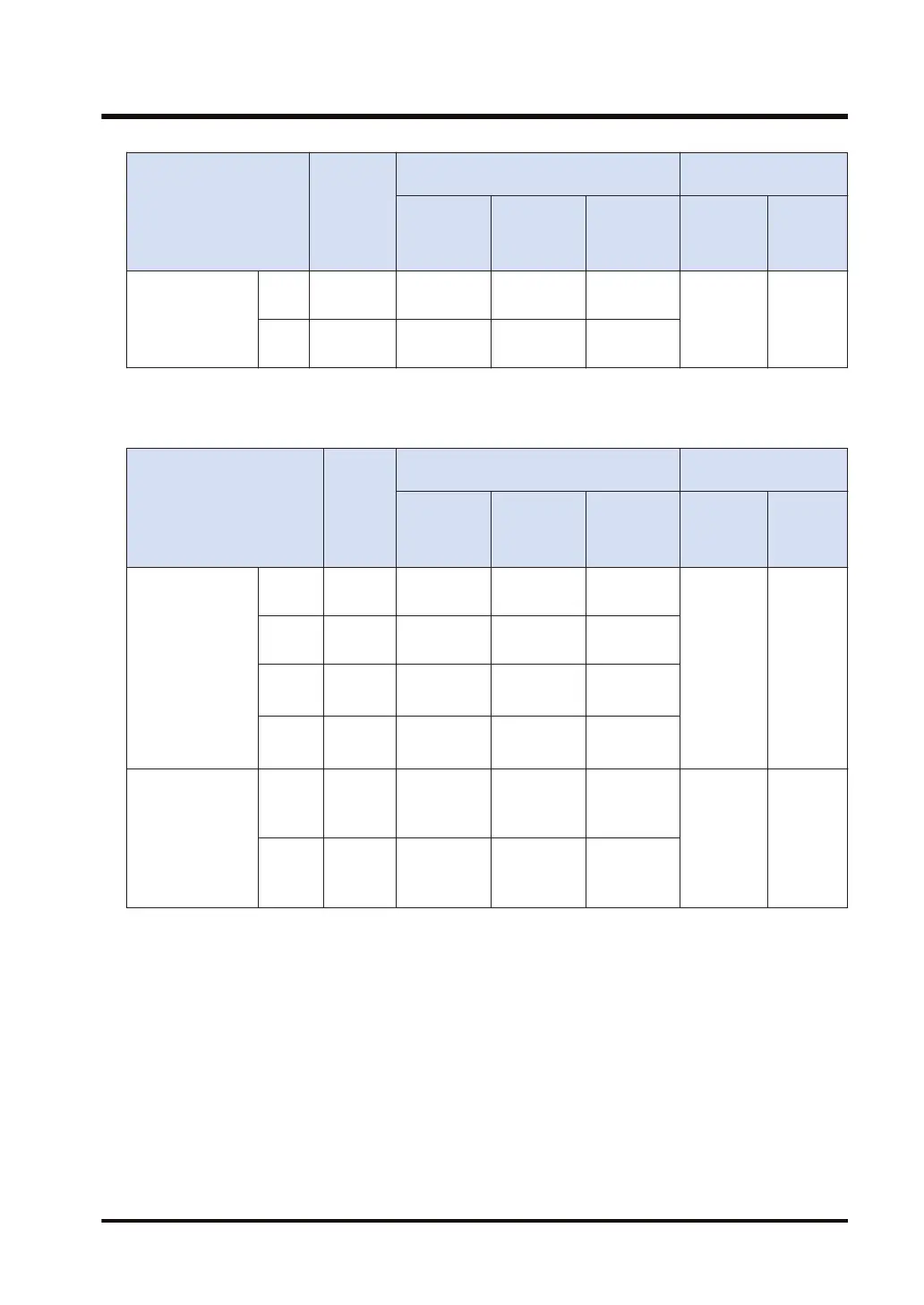
Channel no.
Count
Input
Memory area used
Performance
Specifications
Control
active
flag
Elapsed
value
area
Target value
area
Minimum
input
pulse
width
Maximum
counting
speed
CH4
X4
X5
R9114
DT90316
DT90317
DT90318
DT90319
CH6
X6
X7
R9116
DT90324
DT90325
DT90326
DT90327
(Note 1) Only F1 (DMV) instruction can perform the reading and writing of elapsed value area.
■
When using the relay output type pulse I/O cassette
Channel no.
Input
contact
(Note 1)
Memory area used
Performance
specifications
Control
active
flag
Elapsed
value
area
Target value
area
Minimum
input
pulse
width
Maximum
counting
speed
[Single phase]
Addition input
Subtraction input
CH8
X100
(X102)
R9118
DT90332
DT90333
DT90334
DT90335
6.25μs
(100 μs)
Single-
phase 2
channels
100 kHz
Single-
phase 4
channels
100 kHz
CH9
X101
(X102)
R9119
DT90336
DT90337
DT90338
DT90339
CHA
(Note 2)
X200
(X202)
R911A
DT90340
DT90341
DT90342
DT90343
CHB
(Note 2)
X201
(X202)
R911B
DT90344
DT90345
DT90346
DT90347
[2-phase]
Phase differential
input
Individual input
direction
distinction
CH0
X100
X101
(X102)
R9118
DT90332
DT90333
DT90334
DT90335
16.7 μs
(100 μs)
2-phase 1
channel
50 kHz
2-phase 2
channels
10 kHz
CH2
(Note 2)
X200
X201
(X202)
R911A
DT90340
DT90341
DT90342
DT90343
(Note 1) The I/O numbers shown in parentheses can be used as the hardware reset input for one of the
channels.
(Note 2) CHA or CHB can be used when two pulse I/O cassettes are installed.
(Note 3) Only F1 (DMV) instruction can perform the reading and writing of elapsed value area.
11.2 Allocation of Memory Areas
WUME-FPXHPOSG-01 11-11

 Loading...


