■
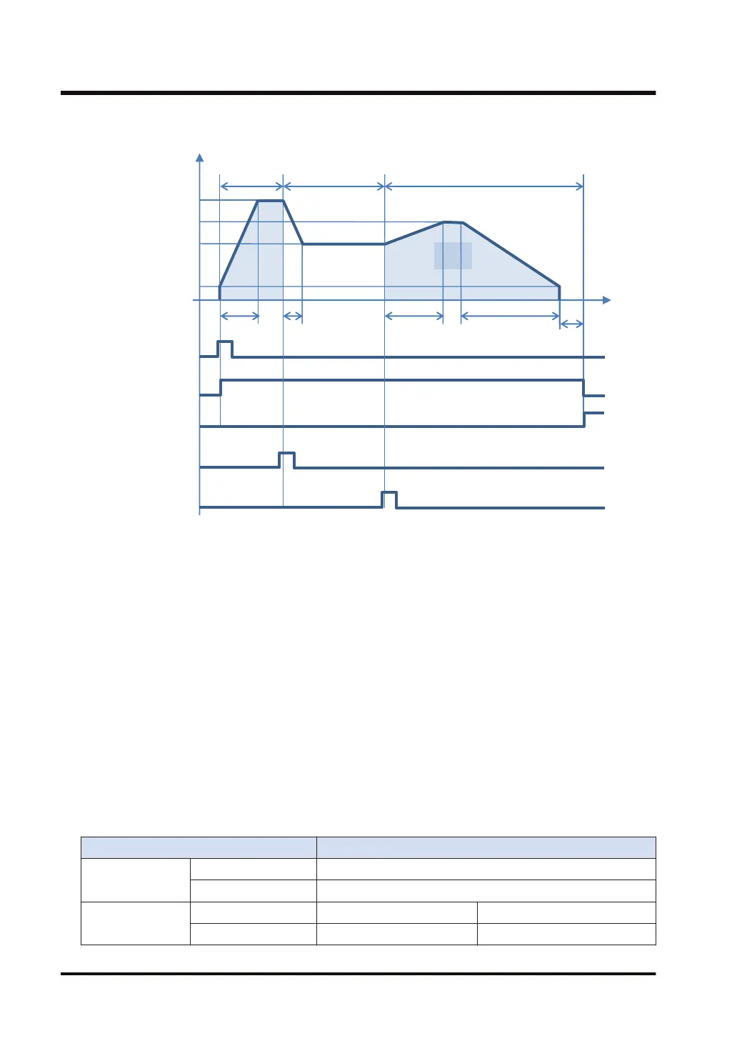
Operation diagram
t [ms]
f [Hz]
100ms
50ms
20,000Hz
1,000Hz
10,000Hz
Approx. 50 ms
250ms
100000
pulses
150 ms
15,000Hz
J-point speed
change
J-point speed
change contact
J-point positioning
start contact
Instruction
start condition
Busy signal
Operation
done signal
Table 1
Table 2
■
Operations of each contact
● The BUSY flags (X28 and X29) will turn ON when the operation starts and turn OFF when
the operation is completed.
● The operation done flags (X30 and X31), which indicate the completion of operation, will turn
ON when the current operation is completed, and they will be held until the next positioning
control, JOG operation or home return operation starts.
● The target speed will be changed when the J-point speed change contacts (Y60 and Y61)
turn ON. The change will be enabled at the edge where the contact turns ON.
● Positioning control will start when J-point positioning start contacts (X0 and X1) turn ON.
■
Characteristics of acceleration / deceleration zone when changing speeds
● The speed of speed change zone changes for each scan when changing the speed in the J-
point control. The speed variation is obtained by the following formula.
(J-point table target speed - Startup speed) / (J-point table acceleration time or J-point table
deceleration time)
■
Settings
Item Setting example
Axis setting area
Startup speed 1,000 Hz
J-point change speed 10,000 Hz
Table area
Table number Table 1 Table 2
Control method Increment mode Increment mode
5.4 Positioning Control
5-24 WUME-FPXHPOSG-01

 Loading...


