Page 3-26
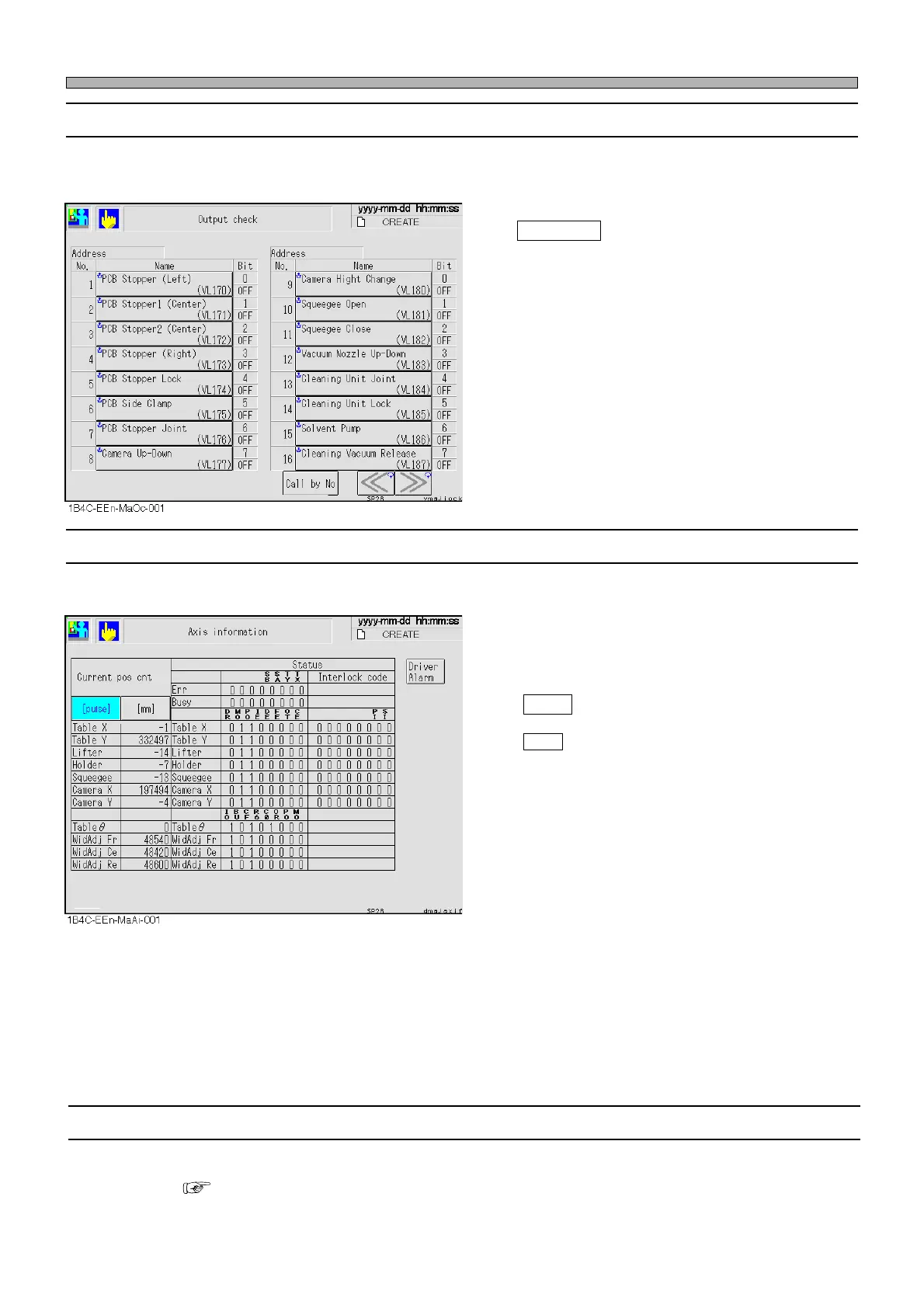
3-4-13 Axis Information
This is used to check the positions and status information of all the axes the machine controls.
<Descriptions of Items>
Current pos cnt
Displays the current position of each axis in
mm or pulse of status address.
pulse : Displays the current position in
pulse.
mm : Displays the current position in mm.
Status
Displays the state of status address, error/busy
of each axis, in bit form.
Machine Adjustment
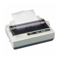
3-4-12 Output Check
This is used to check the states of the valves which are used frequently in adjustment and check
each motion by working each of them individually.
Call by No
Displays the address that includes the speci-
fied No. at the left side of screen.
∗ The states of the output addresses the ma-
chine uses are displayed with names for each
bit.
A highlighted name shows its bit is ON (1).
<Meaning of abbreviation>
SB : Stage B PO : Plus overrun IO : INT outputting
SA : Stage A IE : Interlock error BU : Busy
TY : Table Y DE : Data error CF : Stable frequency
TX : Table X FE : Feedback error R6 : Selecting R6
DR : Driver error OT : Origin returning time over C0 : Counter = 0
MO : Minus overrun CE : Counter error OR : Current origin position
PT : Positioning time over
3-4-14 Recognition Device Maintenance
This is used to maintain the recognition device and check its motion.
( Appendix A RECOGNITION DEVICE (HGR-10) A-5 Recognition Device Maintenance)
1E4C-E-OMA03-A02-01