Subject to reasonable modifications due to technical advances. © Pepperl+Fuchs, Printed in Germany
11
Pepperl+Fuchs Group · Tel.: Germany (6 21) 7 76-0 · USA (3 30) 4 25 35 55 · Singapore 7 79 90 91 Internet http://www.pepperl-fuchs.com
Issue date: 17.4.2009
AS-Interface
General
2.2 Brief description
The actuator-sensor interface (AS-i) has established itself as a system for net-
working primarily binary sensors and actuators at the lowest level of the automa-
tion hierarchy. The high number of installed systems, the ease of use and the reli-
able operating behaviour also make the AS-i interesting in the area of machine
safety.
The safety AS-i system is intended for safety applications up to Category 4/
SIL 3. Mixed operation of standard components and safe components is possible.
The AS-i/Gateways with integrated Safety Monitor monitors within an AS-i system
the safe slaves which have been assigned according to the configuration speci-
fied by the user with the configuration software. In the event of a stop request or a
defect, the AS-i/Gateways with integrated Safety Monitor switches off the system
in protective operation mode with a maximum reaction time of 40 ms.
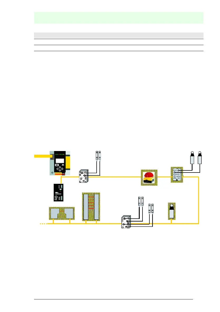
Fig. 2-1. Safe and standard components in an AS-i network
Multiple AS-i Safety Monitors can be used within an AS-i system. In this way, a
safe slave can be monitored by multiple AS-i Safety Monitors.
SaW outputs: number of SaW outputs
Safety relays: number of safety relays
Caption
Tab. 2-3.
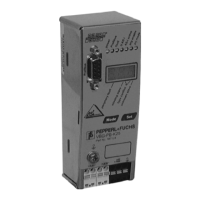
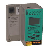
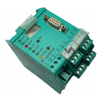
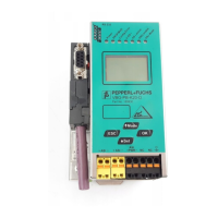
AS-i/Gateway with integrated Safety Monitor
AS-i power
supply unit
Protective photoelectric
sensor
Standard
module
Standard
module
Protective photoelectric
light barrier
Safety emergency
shutdown switches
Safety
module
Safety position
switch
 Loading...