Subject to reasonable modifications due to technical advances. © Pepperl+Fuchs, Printed in Germany
43
Pepperl+Fuchs Group · Tel.: Germany (6 21) 7 76-0 · USA (3 30) 4 25 35 55 · Singapore 7 79 90 91 Internet http://www.pepperl-fuchs.com
Issue date: 17.4.2009
AS-Interface
Electrical connection
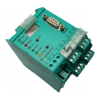
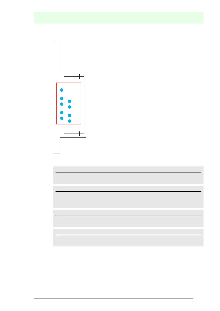
7.9.2 LED indicators - monitor
The LED’s on the safety unit indicate:
1.Y1
Aux
2.Y1
K1
K3
1.Y2
2.Y2
K2
K4
2.13
+
24 V
2.Y1
0 V
+
1.13
2.Y2
1.Y2
2.14
+
4.14
+
1.14
1.Y1
3.14
Aux
24 V supply for the semiconductor outputs is present.
1Y.1, 1Y2, 2Y.1, 2Y.2
Input 1.Y1 (EDM 1/Start 1), 2.Y1 (EDM 2/Start 2), 1.Y2 (EDM 3/Start 3),
2.Y2 (EDM 4/Start 4) is turned on.
K1, K2
Contact sets 1.13, 1.14 (K1) resp. 2.13, 2.14 (K2) closed.
K3, K4
Auxiliary voltage is present on the semiconductor output 3.14 (K3) resp.4.14 (K4).
 Loading...