MAINTENANCE PROCEDURES : MAIN CONTROL UNIT (MCU) ASSEMBLY REMOVAL
02.9687.0010 0 27
2
Main Control Unit (MCU) Assembly Removal
WARNING: Ensure that power is completely removed (disconnected) from luminaire before
attempting any work.
To remove MCU assembly:
CAUTION: When handling printed circuit boards (such as the MCU assembly) make sure to follow
appropriate precautions to protect them ESD damage.
Step 1. Remove power from luminaire and allow unit to completely cool.
Step 2. Remove front cover assembly as described in “Front Cover Assembly Removal” on page 19.
Step 3. At MCU assembly, disconnect the following cable assemblies:
a. 36Vdc - Connector J7
b. DMX - Connector J10
c. Display Com - Connector J11
d. Ballast Com - Connector J8
e. Head Fans (VL770/880 luminaires only) - Connector J5
f. Wireless Accessory - Connector J12
g. Lamp Fans - Connector J6
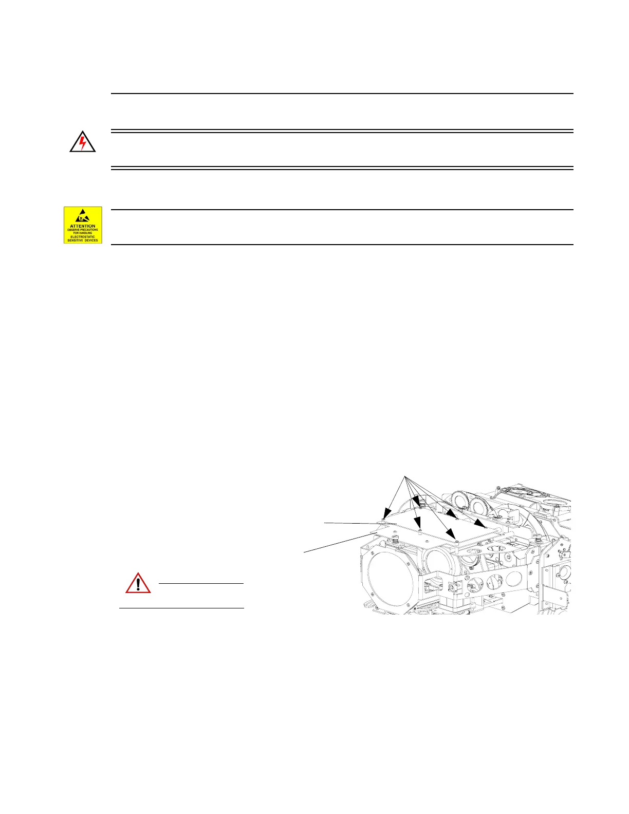
Step 4. Remove six 4-40 x 1/2" PPZ screws (as indicated in Figure 2-10).
Figure 2-10: MCU Assembly Removal
Step 5. Carefully disconnect MCU from Driver Board and remove from luminaire.
Step 6. Replace by performing steps in reverse order.
CAUTION:
Remove power and
allow fixture to cool.
4-40 x 1/2" PPZ Screws
Driver Board Assembly
MCU Board Assembly