MAINTENANCE PROCEDURES : DISPLAY PCB ASSEMBLY REPLACEMENT
02.9687.0010 0 65
2
Display PCB Assembly Replacement
WARNING: Ensure that power is completely removed (disconnected) from luminaire before
attempting any work.
To remove the display PCB assembly:
Step 1. Ensure power is completely removed from luminaire and luminaire has cooled completely.
Step 2. Remove Ballast / LVS assembly as described in “Ballast / LVS Assembly Replacement” on
page 60.
WARNING: Do not set head on or damage front lens during next step!
Step 3. Carefully, flip luminaire to access bottom of enclosure. Do not set on lens.
Step 4. Remove six 1/4-20 x 1/2" PFZ screws and remove Bottom Plate from enclosure assembly.
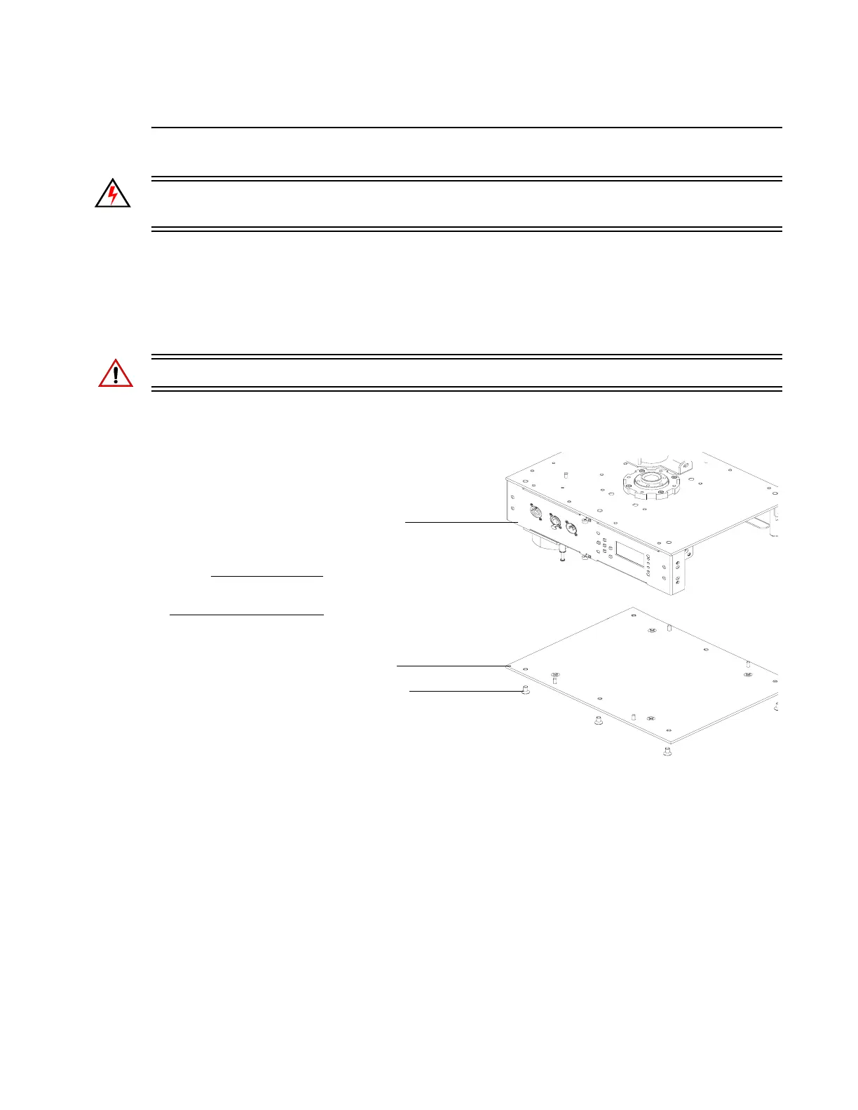
Figure 2-48: Enclosure Assembly Bottom Plate Removal
Step 5. At Display PCB assembly, disconnect all wiring.
NOTE:
Components removed and
exploded for clarity.
Enclosure Assembly
1/4-20 x 1/2" PFZ Screw (x6)
Bottom Plate