VARI❋LITE - VL440 / VL770 / VL880 SPOT LUMINAIRES SERVICE MANUAL
34 02.9687.0010 0
Tilt Motor Assembly / Tilt Encoder / Tilt Belt Removal
WARNING: Ensure that power is completely removed (disconnected) from luminaire before
attempting any work. Wear protection on hands (soft cotton gloves) when handling glass.
To remove tilt motor assembly:
Step 1. Remove power from luminaire and allow unit to completely cool.
Step 2. Remove front and rear cover assemblies (see “Front Cover Assembly Removal” on page 19
and “Rear Cover Assembly Removal” on page 20).
Step 3. Remove Gobo Module Assembly as described in “Gobo Module Assembly Removal” on
page 23.
Step 4. Remove CYMD Module Assembly as described in “CYMD Module Assembly Removal”
on page 24.
Step 5. Remove Zoom Module Assembly as described in “Zoom Module Assembly Removal” on
page 25.
Step 6. Cut cable tie connecting wiring to bottom of motor assembly.
Step 7. Disconnect wiring from motor assembly and tilt encoder PCB.
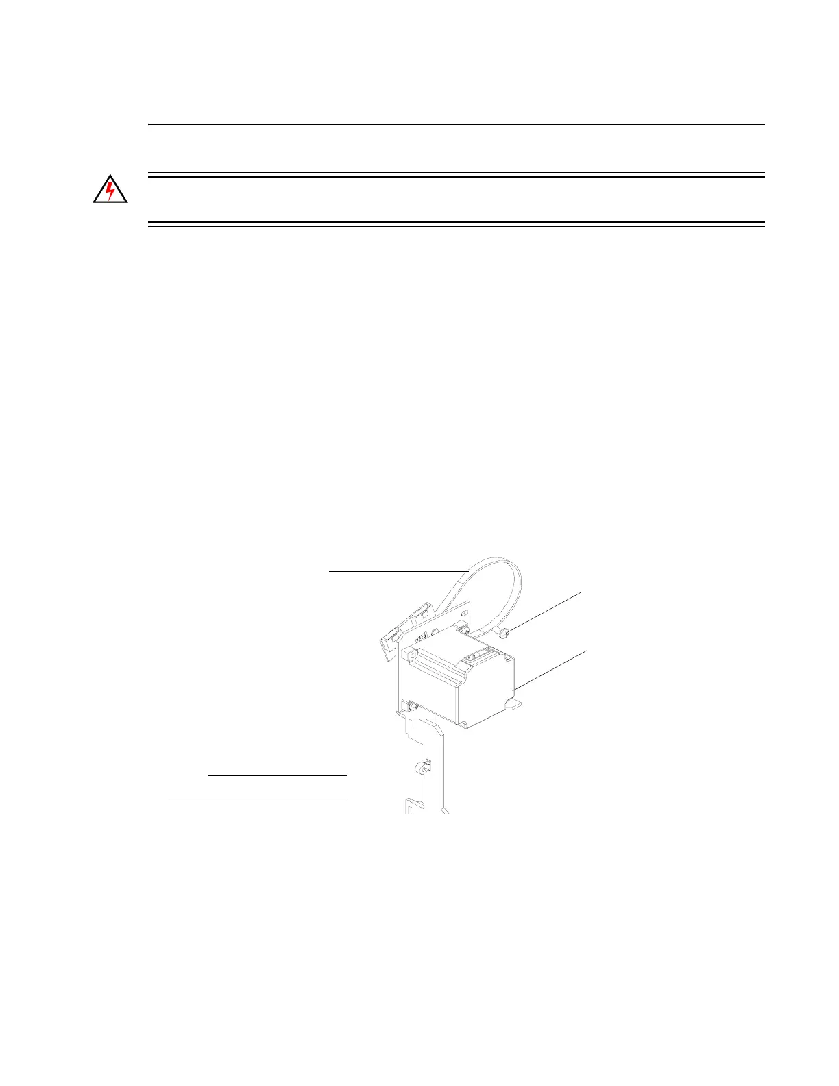
Step 8. As shown in Figure 2-16, remove three 8-32 x 3/8" PPB SEMS screws.
Figure 2-16: Tilt Motor Assembly Removal
Step 9. Carefully, remove tilt belt from pulley and remove motor assembly. Note, when installing,
loop tilt belt around pulley.
Step 10. Start all three 8-32 x 3/8" PPB SEMS screws but do not tighten at this time.
Step 11. Insert flat blade screwdriver into slot between bottom two screws and pull motor assembly
to tighten belt tension (should be tight). Then tighten three 8-32 x 3/8" PPB SEMS screws.
Step 12. Continue reassembly by following previous steps in reverse order.
NOTE:
Components removed for clarity.
8-32 x 3/8" PPB
SEMS Screw (x3)
Tilt Motor
Assembly
Tilt Encoder PCB
Tilt Belt