Point Grey Flea3 USB 3.0 Technical Reference 7 Imaging Parameters and Control
7.11 Bayer Color Processing
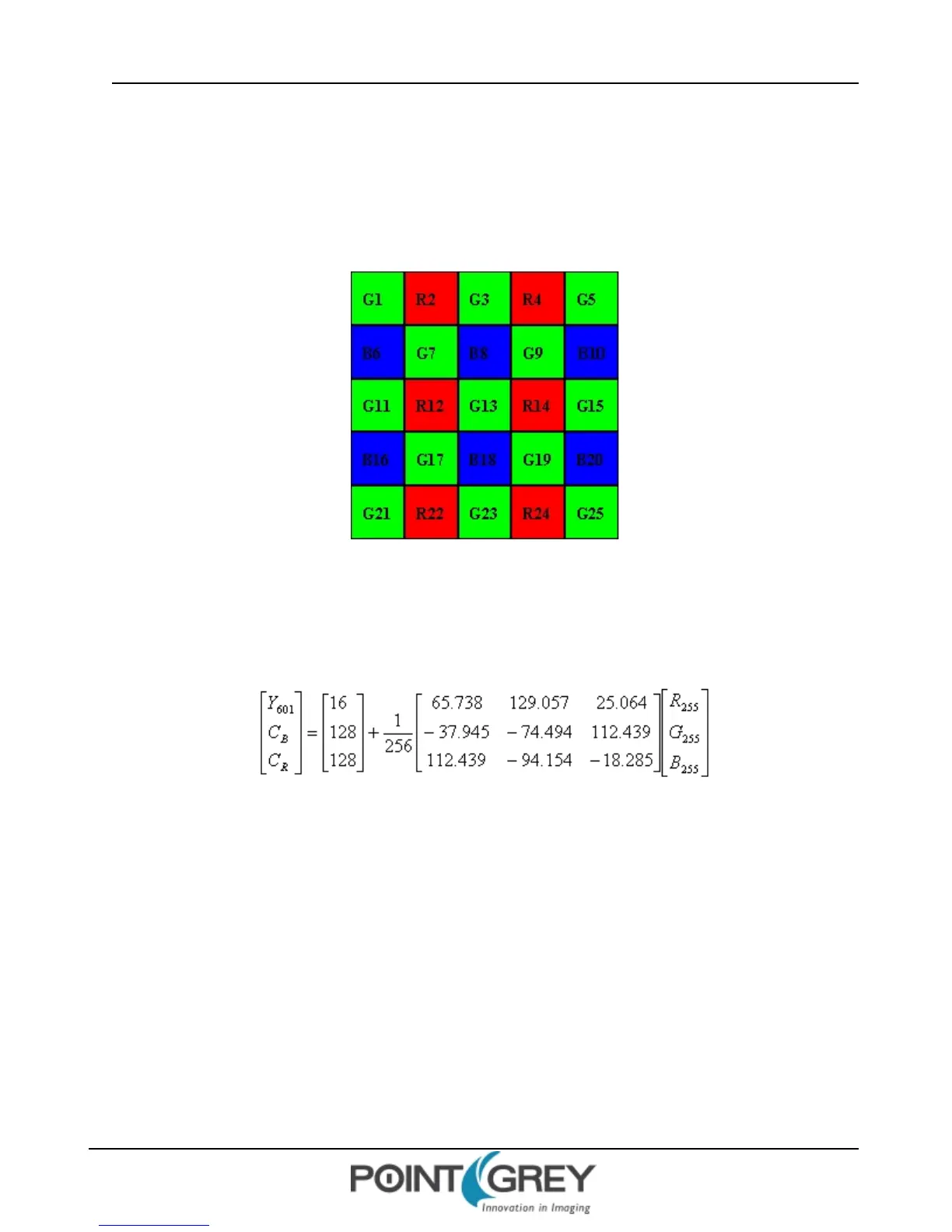
In color models, a Bayer tile pattern color filter array captures the intensity red, green or blue in each pixel on the
sensor. The image below is an example of a Bayer tile pattern.
To determine the actual pattern on your camera, query the BAYER_TILE_MAPPING register 1040h (page 118).
Figure 7.1: Example Bayer Tile Pattern
In order to produce color (e.g. RGB, YUV) and greyscale (e.g. Y8, Y16) images, color models perform on-board
processing of the Bayer tile pattern output produced by the sensor.
Conversion from RGB to YUV uses the following formula:
To convert the Bayer tile pattern to greyscale, the camera adds the value for each of the RGB components in the color
processed pixel to produce a single greyscale (Y) value for that pixel, as follows:
Y = R/4 + G/2 + B/4
7.11.1 Accessing Raw Bayer Data
Users interested in accessing the raw Bayer data to apply their own color conversion algorithm or one of the
FlyCapture library algorithms should acquire images using one of the Format 7 video modes that support Raw pixel
encoding. (See Supported Formats, Modes and Frame Rates on page 69.)
The actual physical arrangement of the red, green and blue "pixels" for a given camera is determined by the
arrangement of the color filter array on the imaging sensor itself. The format, or order, in which this raw color data is
streamed out, however, depends on the specific camera model and firmware version.
Revised 9/27/2012
Copyright ©2011-2012 Point Grey Research Inc.
117