Point Grey Flea3 USB 3.0 Technical Reference 4 Input/Output Control
Offset Name Field Bit Description
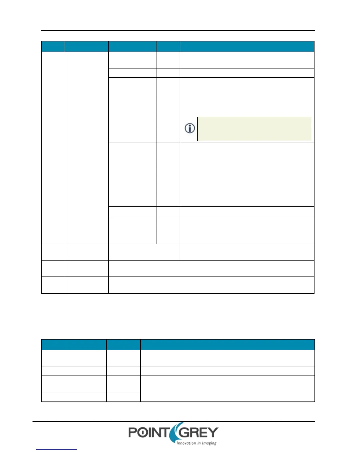
Base +
200h
STROBE_0_CNT
Presence_Inq [0]
Presence of this feature
0: Not Available, 1: Available
[1-5] Reserved
On_Off [6]
Read: read a status
Write: ON or OFF this function
0: OFF, 1: ON
If this bit = 0, other fields will be read only.
When ON, strobe signals continue to output after the
camera stops streaming images. To stop strobe
output, this bit must be explicitly turned OFF.
Signal_Polarity [7]
Select signal polarity
If Polarity_Inq = 1:
Read to get strobe output polarity
Write to change strobe output polarity
If Polarity_Inq = 0, then Read only
0: Low active output, 1: High active output
Delay_Value [8-19] Delay after start of exposure until the strobe signal asserts
Duration_Value [20-31]
Duration of the strobe signal
A value of 0 means de-assert at the end of exposure, if
required.
Base +
204h
STROBE_1_CNT
Same definition as Strobe_0_
Cnt
Base +
208h
STROBE_2_CNT Same definition as Strobe_0_Cnt
Base +
20Ch
STROBE_3_CNT Same definition as Strobe_0_Cnt
4.3.4.2 GPIO_STRPAT_CTRL: 110Ch
This register provides control over a shared 4-bit counter with programmable period. When the Current_Count equals
N a GPIO pin will only output a strobe pulse if bit[N] of the GPIO_STRPAT_ MASK_PIN_ x register’s Enable_Pin field is
set to ‘1’.
Field Bit Description
Presence_Inq [0]
Presence of this feature
0: Not Available, 1: Available
[1-18] Reserved
Count_Period [19-23]
Controls the period of the strobe pattern
Valid values: 1..16
[24-27] Reserved
Revised 9/27/2012
Copyright ©2011-2012 Point Grey Research Inc.
48