Point Grey Flea3 USB 3.0 Technical Reference 4 Input/Output Control
4.3.4 Strobe Signal Output Registers
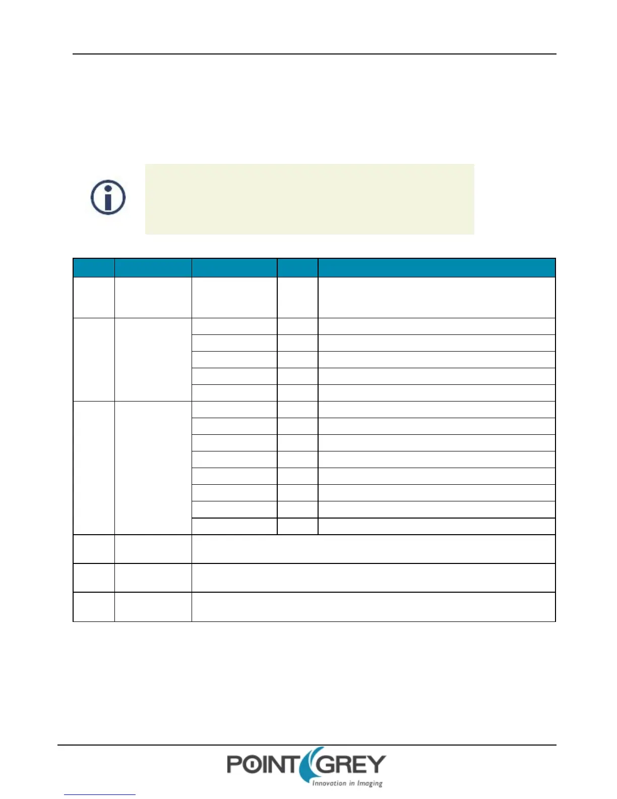
This section describes the control and inquiry registers for the Strobe Signal functionality.
4.3.4.1 Strobe Output Registers
To calculate the base address for an offset CSR:
1. Query the offset inquiry register.
2. Multiple the value by 4. (The value is a 32-bit offset.)
3. Remove the 0xF prefix from the result. (i.e., F70000h becomes 70000h)
Offset Name Field Bit Description
48Ch
STROBE_
OUTPUT_CSR_
INQ
Strobe_Output_
Quadlet_Offset
[0-31]
32-bit offset of the Strobe output signal CSRs from the base
address of initial register space
Base +
0h
STROBE_CTRL_
INQ
Strobe_0_Inq [0] Presence of strobe 0 signal
Strobe_1_Inq [1] Presence of strobe 1 signal
Strobe_2_Inq [2] Presence of strobe 2 signal
Strobe_3_Inq [3] Presence of strobe 3 signal
- [4-31] Reserved
Base +
100h
STROBE_0_INQ
Presence_Inq [0] Presence of this feature
[1-3] Reserved
ReadOut_Inq [4] Ability to read the value of this feature
On_Off_Inq [5] Ability to switch feature ON and OFF
Polarity_Inq [6] Ability to change signal polarity
[7] Reserved
Min_Value [8-19] Minimum value for this feature control
Max_Value [20-31] Maximum value for this feature control
Base +
104h
STROBE_1_INQ Same definition as Strobe_0_Inq
Base +
108h
STROBE_2_INQ Same definition as Strobe_0_Inq
Base +
10Ch
STROBE_3_INQ Same definition as Strobe_0_Inq
Format:
Revised 9/27/2012
Copyright ©2011-2012 Point Grey Research Inc.
47