Point Grey Flea3 USB 3.0 Technical Reference 4 Input/Output Control
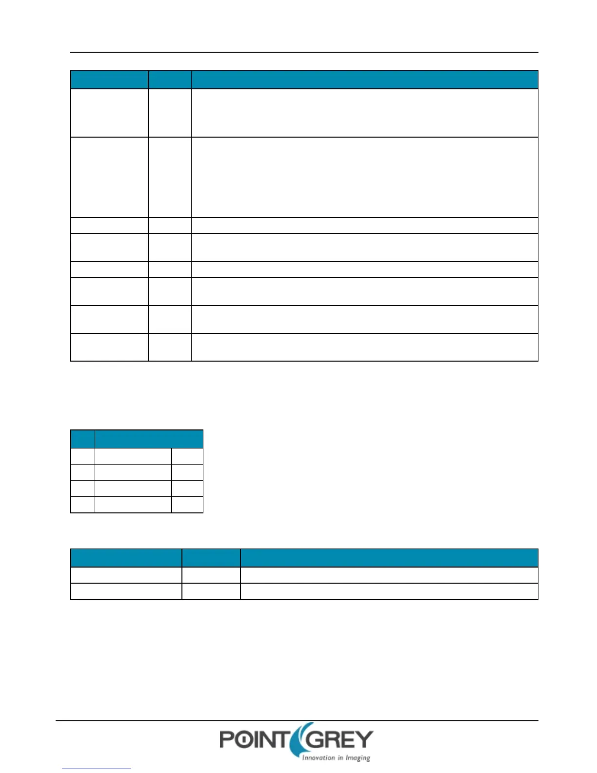
Field Bit Description
Data [31]
For Modes 0, 1, and 2: Data field
0 = 0 V (falling edge), 1 = +3.3 V (rising edge)
For Mode 4 (PWM): see below
Pwm_Count [16-23]
Number of PWM pulses
Read: The current count; counts down the remaining pulses. After reaching zero, the count
does not automatically reset to the previously-written value.
Write: Writing the number of pulses starts the PWM. Write 0xFF for infinite pulses. (Requires
write of 0x00 before writing a different value.)
[24] Reserved
En_Pin [25-27]
The GPIO pin to be used as a PWM enable i.e. the PWM continues as long as the En_Pin is
held in a certain state (high or low).
[28] Reserved
Disable_Pol [29]
Polarity of the PWM enable pin (En_Pin) that will disable the PWM. If this bit is 0, the PWM is
disabled when the PWM enable pin goes low.
En_En [30]
0: Disable enable pin (En_Pin) functionality
1: Enable En_Pin functionality
Pwm_Pol [31]
Polarity of the PWM signal
0: Low, 1: High
4.4.2 GPIO_XTRA_PIN: 1114h-1144h
These registers contain mode specific data for the GPIO pins. Units are ticks of a 1.024MHz clock.
Pin Register
0 GPIO_XTRA_PIN_0 1114h
1 GPIO_XTRA_PIN_1 1124h
2 GPIO_XTRA_PIN_2 1134h
3 GPIO_XTRA_PIN_3 1144h
Field Bit Description
Mode_Specific_1 [0-15] GPIO_MODE_4: Low period of PWM pulse (if Pwm_Pol = 0)
Mode_Specific_2 [16-31] GPIO_MODE_4: High period of PWM pulse (if Pwm_Pol = 0)
Format:
4.5 Serial Communication
The camera is capable of serial communications at baud rates up to 115.2 Kbps via the on-board serial port built into
the camera’s GPIO connector. The serial port uses TTL digital logic levels. If RS signal levels are required, a level
converter must be used to convert the TTL digital logic levels to RS voltage levels.
Revised 9/27/2012
Copyright ©2011-2012 Point Grey Research Inc.
51