Point Grey Flea3 USB 3.0 Technical Reference 1 Welcome to Flea3 USB 3.0
1.5 Camera Interface and Connectors
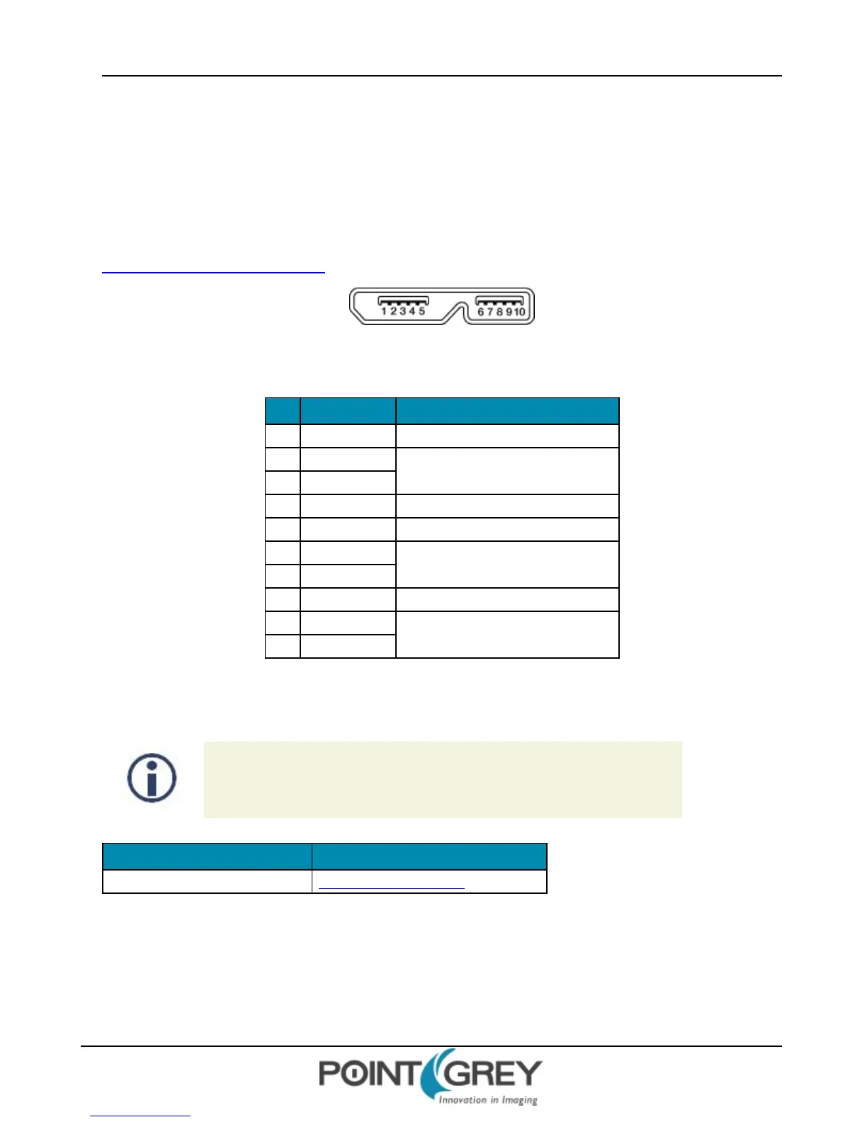
1.5.1 USB3.0 Connector
The camera is equipped with a USB 3.0 Micro-B connector that is used for data transmission, camera control and
power. For more detailed information, consult the USB 3.0 specification available from
http://www.usb.org/developers/docs/.
Figure 1.14: USB 3.0 Micro B Connector
Table 1.2: USB 3.0 Micro-B Connector Pin Assignments
Pin Signal Name Description
1 VBUS Power
2 D-
USB 2.0 differential pair
3 D+
4 ID OTG identification
5 GND Ground for power return
6 MicB_SSTX-
SuperSpeed transmitter differential pair
7 MicB_SSTX+
8 GND_DRAIN Ground for SuperSpeed signal return
9 MicB_SSRX-
SuperSpeed receiver differential pair
10 MicB_SSRX+
The USB 3.0 Micro-B receptacle accepts a USB 2.0 Micro-B plug and, therefore, the camera is backward compatible
with the USB 2.0 interface.
When the camera is connected to a USB 2.0 interface, it runs at USB2.0 speed,
and maximum frame rates are adjusted accordingly based on current imaging
parameters.
Title Article
USB 3.0 Frequently Asked Questions
Knowledge Base Article 357
Related Knowledge Base Articles
1.5.2 Interface Card
The camera must connect to an interface card. This is sometimes called a host adapter, a bus controller, or a network
interface card (NIC).
Revised 9/27/2012
Copyright ©2011-2012 Point Grey Research Inc.
20