Point Grey Flea3 USB 3.0 Technical Reference 4 Input/Output Control
As an example, if the output trigger is a strobe light, the light from the second frame will appear in the first frame as
well. To reduce this effect, slow the frame rate to increase the time between frames. If the slower frame rate is not
feasible, or the reduction of the effect not complete, a camera with a global shutter is recommended.
For more information on types of shutters see Global Shutter on page 79 and Rolling Shutter on page 79.
4.3.2 Example: Setting a GPIOPin to Strobe (Using the Camera Registers)
Consider the following example strobe scenario:
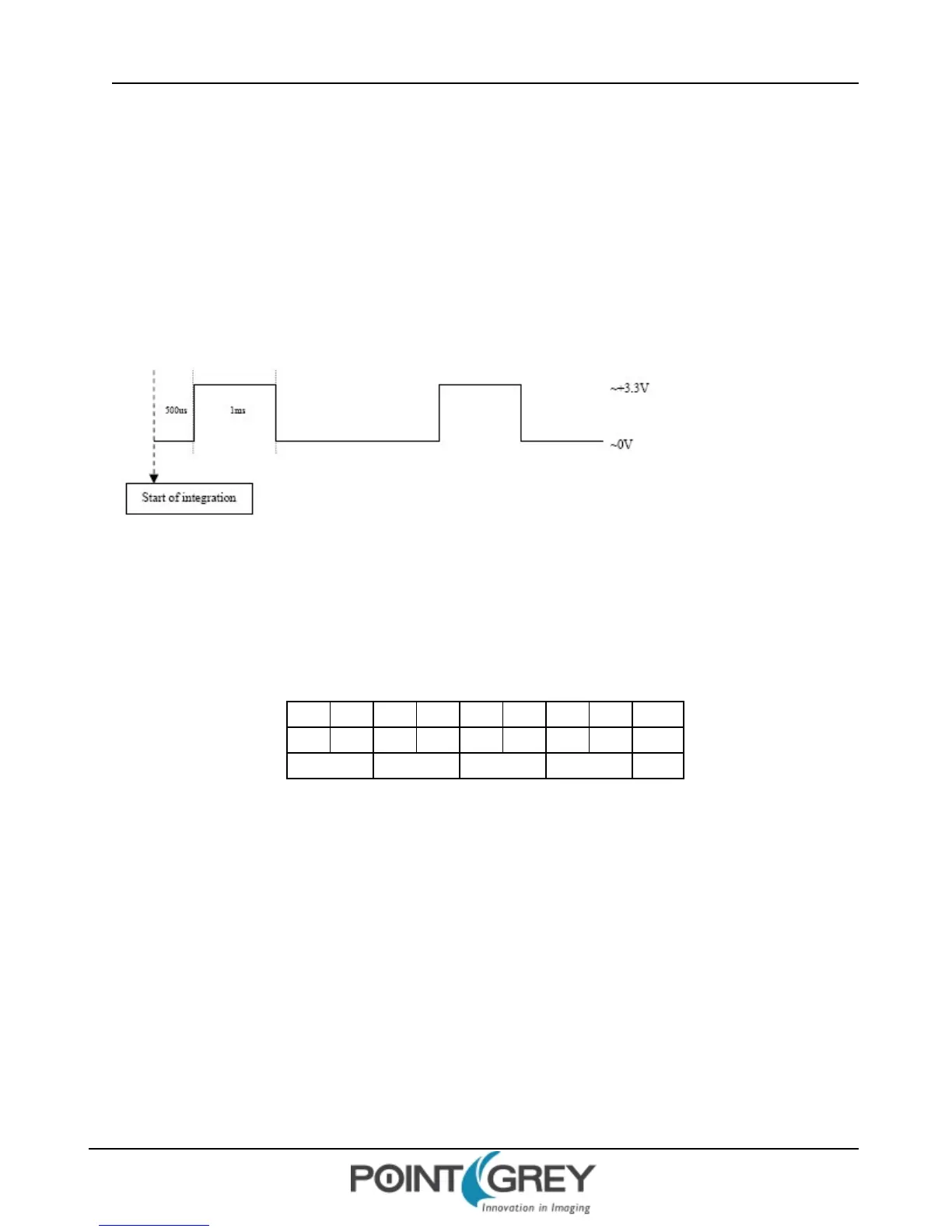
n Desired strobe output pin: GPIO2
n Strobe output characteristics: 500us delay from start of shutter, 1ms high duration (see below)
Determine the Default Output Pins
Electrically, general purpose input/output pins are in one of two states: input or output. In order for a GPIO pin to act
as a strobe output source, it must be configured as an output. To determine which of the GPIO pins are outputs by
default, get the value of the PIO_DIRECTION register 0x11F8 (page 91). The IOx_Mode fields (bits 0-3) report the
current state of the corresponding pin. For example:
4 0 0 0 0 0 0 0 Hex
0100 0000 0000 0000 0000 0000 0000 0000 Binary
0-7 8-15 16-23 24-31 Bits
0x11F8 = 0x4000 0000
Each of the first four bits represents the current state of its associated GPIO pin: ‘0’ indicates it is an input/trigger, and
‘1’ indicates it is an output/strobe. In the example above, 0x4 = 0100 in binary, so GPIO1 is configured as an output and
GPIO0, GIPIO2 and GPIO3 are inputs.
Set the Desired Pin as an Output
Following the example above, assume we want to configure GPIO2 to be an output. To do this, set the appropriate bit
of the PIO_ DIRECTION register 0x11F8 (in this case bit 2) to ‘1’. In the example above, we would therefore do the
following register write:
0x11F8 = 0x6000 0000
Revised 9/27/2012
Copyright ©2011-2012 Point Grey Research Inc.
44