Point Grey Flea3 USB 3.0 Technical Reference 6 Image Acquisition
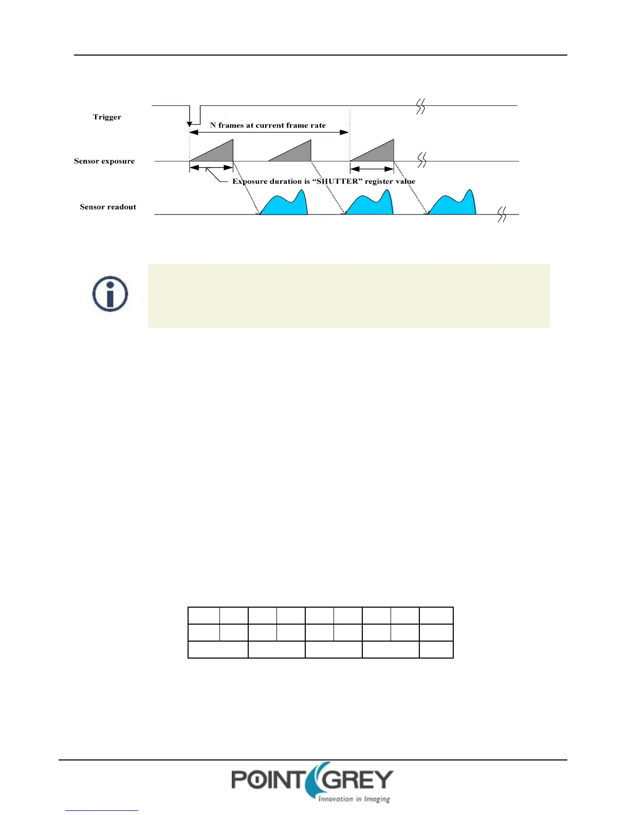
Figure 6.5: Trigger Mode 15 (“Multi-Shot Trigger Mode”)
FL3-U3-32S2 and FL3-U3-88S2 models operating in this trigger mode, if the number of
acquired images is 1, exposure is controlled by the global reset feature of the sensor. This
feature may reduce distortion artifacts typical of rolling shutter sensors. For more
information, see Rolling Shutter Artifacts on page 128.
6.4.7 Example: Asynchronous Hardware Triggering (Using the Camera Registers)
The following example illustrates how to synchronize image acquisition to a trigger from an external hardware device
in Trigger Mode 0 (page 84).
Determine the Default External Trigger Pin
One of the camera GPIO pins is configured as the default trigger. To determine which pin is the default input/trigger
pin either:
1. See General Purpose Input/Output; or
2. Get the value of the TRIGGER_MODE register 0x830 (page 90). The Trigger_Source field (bits 8-10) is the
current trigger source. For example, if the value represented by the Trigger_Source field is 0, the default
trigger source is GPIO0.
For example:
8 0 1 0 0 0 0 0 Hex
1000 0000 0001 0000 0000 0000 0000 0000 Binary
0-7 8-15 16-23 24-31 Bits
0x830 = 0x80100000
This indicates that a Trigger Mode is available (bit 0 = 1) but not currently enabled (bit 6 = 0). It also indicates that
GPIO0 is the default trigger pin (bits 8-10 = 0), and the default polarity of the pin is active low (bit 7 = 0), which means
the camera will trigger on the falling edge of a pulse.
Revised 9/27/2012
Copyright ©2011-2012 Point Grey Research Inc.
86