Point Grey Flea3 USB 3.0 Technical Reference 4 Input/Output Control
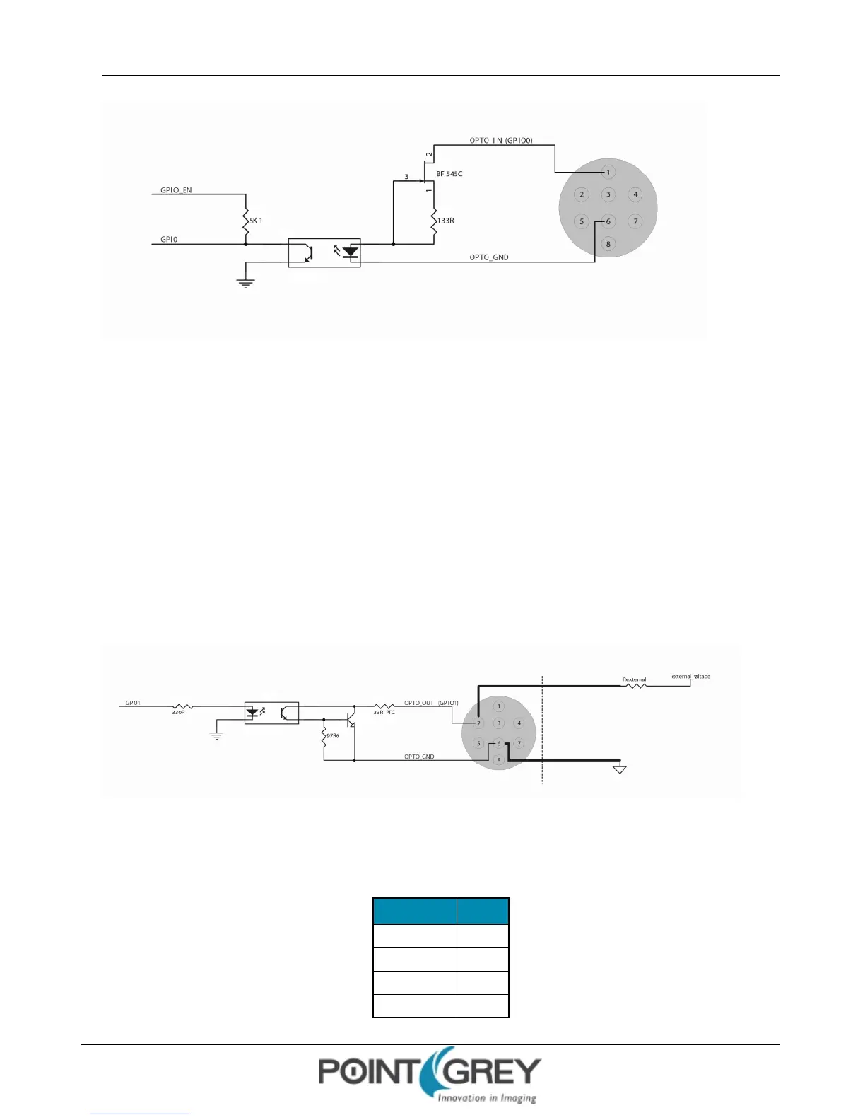
Figure 4.1: Optical input circuit
n Logical 0 input voltage: 0 VDC to +1 VDC (voltage at OPTO_IN)
n Logical 1 input voltage: +1.5 VDC to +24 VDC (voltage at OPTO_IN)
n Maximum input current: 8.3mA
n Behavior between 1 VDC and 1.5 VDC is undefined and input voltages between those values should be avoided
n Input delay time: 4 μs
4.6.2 GPIO1 (Opto-Isolated Output) Circuit
The figure below shows the schematic for the opto-isolated output circuit. The maximum current allowed through the
opto-isolated output circuit is 25 mA.
Figure 4.2: Optical output circuit
The following table lists the switching times for the opto-isolator in the output pin, assuming an output VCC of 5 V and
a 1kΩ resistor.
Parameter Value
Delay Time 9 μs
Rise Time 16.8 μs
Storage Time 0.52 μs
Fall Time 2.92 μs
Revised 9/27/2012
Copyright ©2011-2012 Point Grey Research Inc.
60