Point Grey Flea3 USB 3.0 Technical Reference 4 Input/Output Control
The following table lists several externalvoltage and resistor combinations that have been tested to work with the
opto-isolated output.
External Voltage External Resistor OPTO_OUT Voltage OPTO_OUT Current
3.3 V 1 kΩ 0.56 V 2.7 mA
5 V 1 kΩ 0.84 V 4.2 mA
12 V 2.4 kΩ 0.91 V 4.6 mA
24 V 4.7 kΩ 1.07 V 5.1 mA
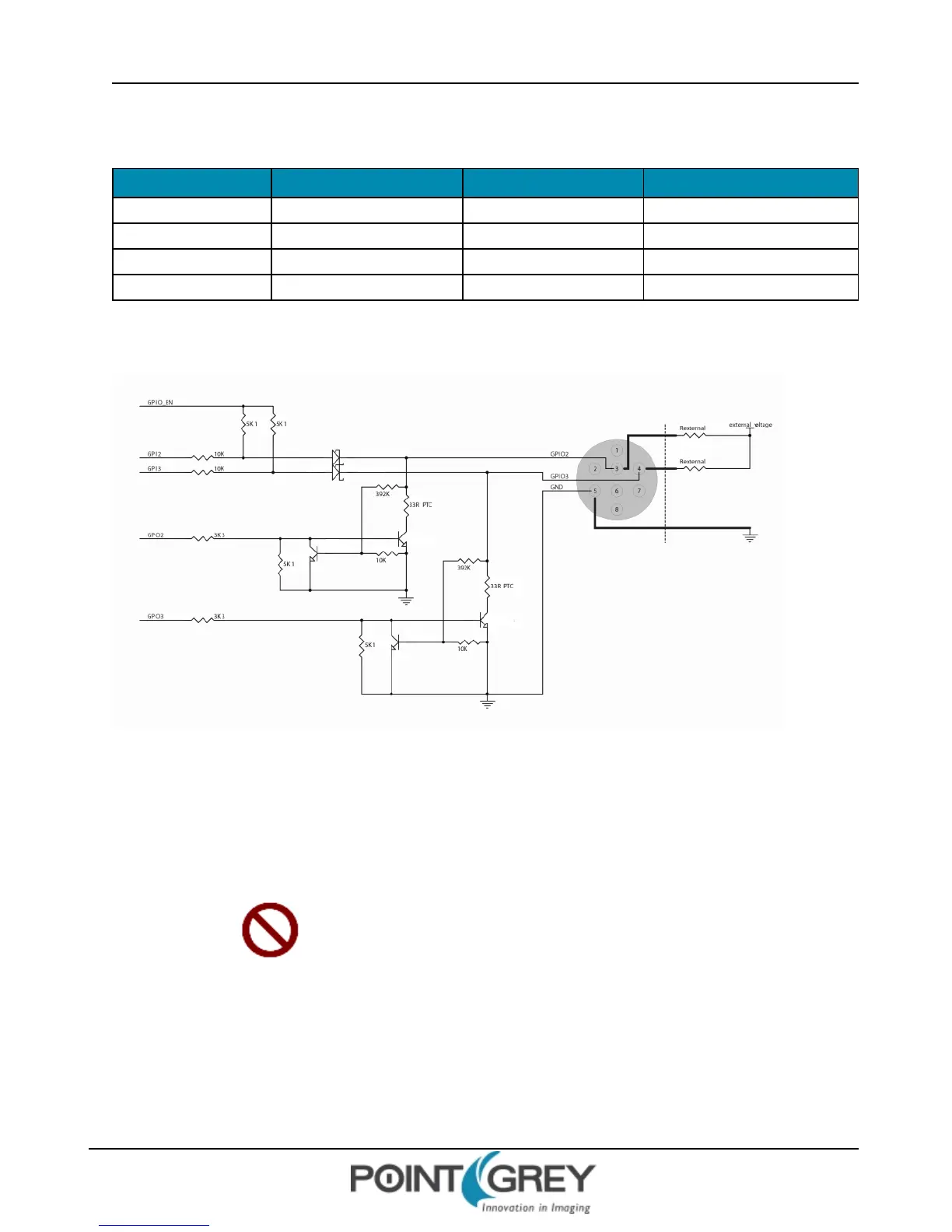
4.6.3 GPIO 2/3 (Bi-Directional) Circuit
Figure 4.3: GPIO2/3 Circuit
Input Side
n Logical 0 input voltage: 0 VDC to +0.5 VDC (voltage at GPIO2/3)
n Logical 1 input voltage: +1.5 VDC to +24 VDC (voltage at GPIO2/3)
n Behavior between 0.5 VDC and 1.5 VDC is undefined and input voltages between those values should be
avoided
To avoid damage, connect the ground (GND) pin first before
applying voltage to the GPIO line.
Output Side
The maximum output current allowed through the bi-directional circuit is 25 mA (limit by PTC resistor), and the output
impedance is 40 Ω.
The following table lists several external voltage and resistor combinations that have been tested to work with the bi-
directional GPIO when configured as output.
Revised 9/27/2012
Copyright ©2011-2012 Point Grey Research Inc.
61