Point Grey Flea3 USB 3.0 Technical Reference Appendix A: Control and Status Registers
Address Name Field Bit Description
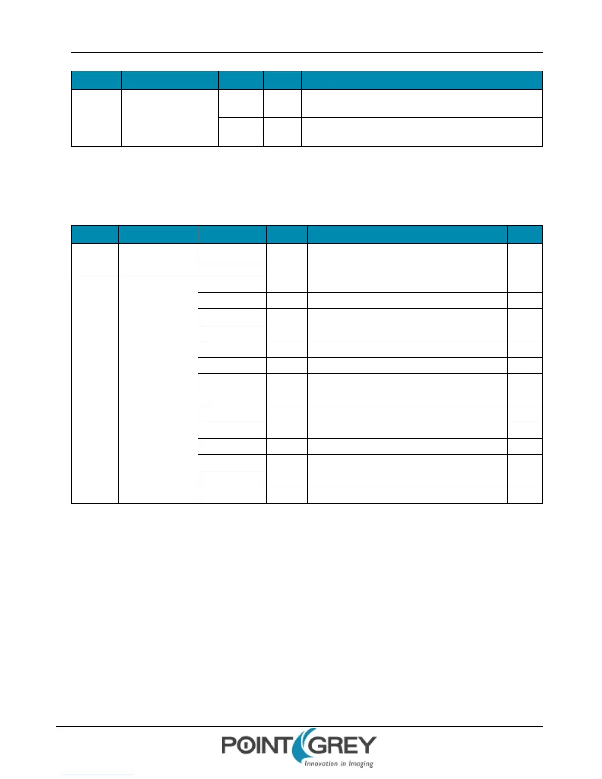
Base +
00Ch
IMAGE_SIZE
Width [0-15]
Width of requested image region (pixels)
Width = Hunit * n2
Height [16-31]
Height of requested image region (pixels)
Height = Vunit * m2 (n1, n2, m1, m2 are integers)
A.3.2.2 COLOR_CODING_ID and COLOR_CODING_INQ
The COLOR_CODING_INQ register describes the color-coding capability of the system. Each coding scheme has its
own ID number. The required color-coding scheme must be set to COLOR_CODING_ID register as the ID number.
Address Name Field Bit Description ID
Base +
010h
COLOR_CODING_
ID
Coding_ID [0-7] Color coding ID from COLOR_CODING_INQ register N/A
[8-31] Reserved N/A
Base +
014h
COLOR_CODING_
INQ
Mono8 [0] Y only. Y=8bits, non compressed 0
4:1:1 YUV8 [1] 4:1:1, Y=U=V= 8bits, non compressed 1
4:2:2 YUV8 [2] 4:2:2, Y=U=V=8bits, non compressed 2
4:4:4 YUV8 [3] 4:4:4, Y=U=V=8bits, non compressed 3
RGB8 [4] R=G=B=8bits, non compressed 4
Mono16 [5] Y only, Y=16bits, non compressed 5
RGB16 [6] R=G=B=16bits, non compressed 6
Signed Mono16 [7] Y only, Y=16 bits, non compressed (signed integer) 7
Signed RGB16 [8] R=G=B=16 bits, non compressed (signed integer) 8
Raw8 [9] Raw data output of color filter sensor, 8 bits 9
Raw16 [10] Raw data output of color filter sensor, 16 bits 10
Mono12 [11] Y only. Y=12 bits, non compressed
Raw12 [12] Raw data output of color filter sensor, 12 bits
[13-31] Reserved 11-31
Format:
A.3.2.3 PACKET_PARA_INQ, BYTE_PER_PACKET, and PACKET_PER_FRAME
If the Presence bit in the VALUE_ SETTING register (page 148) is zero, values of these fields will be updated by writing
the new value to the IMAGE_POSITION, IMAGE_SIZE (page 145) and COLOR_CODING_ID (page 146) registers with the
value of the ISO_Speed register (page 91).
First, the ISO_Speed register must be written. Then the IMAGE_ POSITION, IMAGE_ SIZE and COLOR_CODING_ID
registers should be updated.
If the Presence bit in the VALUE_SETTING register is one, the values of these fields will be updated by writing one to
the Setting_1 bit in the VALUE_SETTING register. If the ErrorFlag_1 bit is zero after the Setting_1 bit returns to zero,
the values of these fields are valid.
Revised 9/27/2012
Copyright ©2011-2012 Point Grey Research Inc.
146
 Loading...


