3.40
ENGINE
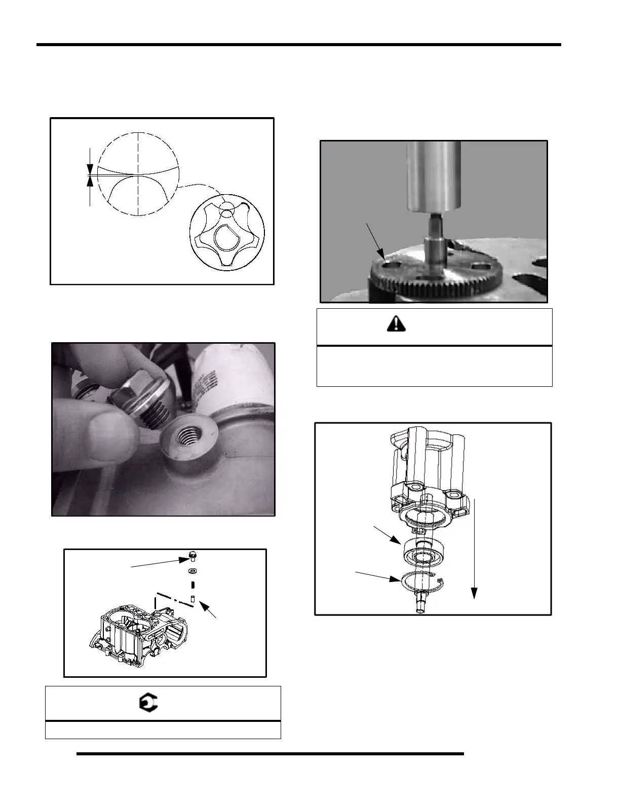
28. Use a feeler gauge to measure the clearance between the
two rotors. Measure the gap between the two rotor tips as
shown below. The clearance should not exceed 0.006"
(0.15 mm).
29. Remove the oil pressure relief. The oil pressure relief
consists of a bolt, washer, spring, and valve (dowel).
Inspect the valve (dowel) for signs of possible obstructions.
Use compressed air to blow out any debris.
30. Reinstall the valve (dowel chamfered end first). Install the
spring, washer, and bolt. Torque to specification .
NOTE: Be sure to place the tapered end of the valve
(dowel) in first. If the valve is installed incorrectly,
oil pressure and oil priming problems will occur.
31. Carefully press the gear off the assembly while supporting
the housing assembly.
32. Remove the snap ring from the assembly. Place the housing
in a support and press out the bearing/shaft assembly.
= T
22 2 ft. lbs. (30 3 Nm)
0.006” (0.15 mm)
Max Tip Clearance
22 22 2 ft. lbs.
(30 3 Nm).
Chamfer
End First
CAUTION
Wear appropriate safety gear during this procedure.
Protective gloves, clothing and eyewear are
required.
Press Off Gear
Press Out shaft
and bearing
assembly.
Bearing
Retaining Ring
 Loading...