6.19
PVT System
6
Roller Removal
1. With the spider in a vise start removing the spider
buttons by drilling a 0.18" hole in the center of a button
on one side of the spider.
2. Place a pin punch through the drilled hole in the button
an
d drive the opposing button and pin out.
3. Remove shims (if any are installed) and note their
loc
ation.
4. Flip the spider over and tap out the holed button.
5. Perform steps on remaining spider legs.
NOTE: When required, button shims are installed on
t
he trailing (right) side of the spider leg as viewed from
the front of spider.
Roller Installation
NOTE: Use care to start the pin straight. Aluminum
burrs could pass through into the roller bushing
causing it to bind and stick. Also use care to make
sure the roller remains aligned when the pin is driven
through. The roller busing could be damaged causing
premature wear and roller failure.
1. Drive pin into the spider leg .100" -.125" (0.25 -
0.3
2cm) beyond the first land of the spider leg.
2. Install one washer on the portion of the pin that is
pr
otruding from the spider leg.
3. Place roller in spider leg and center it on the pin.
4. Place a second washer on the other side of the roller.
5. Place the spider on a vise.
6. Install pin centering tool (PN 2870401).
7. Drive the roller pin through the second land of the
spider.
8. Repeat process for the other two rollers.
Spider Button Installation
1. A shim kit is available which contains an assortment
of shims.
2. Measure the width of the moveable sheave towers
a
nd record. Specification is 1.50"+/- .001" (38.1mm).
3. Measure the width of each corresponding spider leg
with
the buttons installed and record. Specification is
1.496"+/- .001" (37.99mm).
4. Subtract the spider measurement form the tower
m
easurement. The clearance between the spider
buttons and the moveable sheave towers is .001" -
.002" (.025 - .05mm).
5. Add shims beneath each trailing side spider button
to
obtain the specified button-to-tower clearance when
assembled at each spider leg.
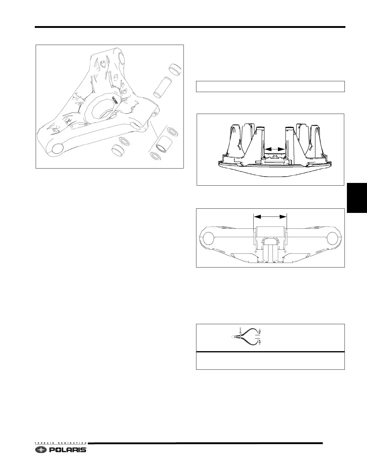
SPIDER
BUTTON
SHIM
WASHER
ROLLER
ROLLER PIN
WASHER
BUTTON
Drive Clutch Shim Kit
PN 2200387
Button-To-Tower Clearance
.001" - .002" (.025 - .05mm)

 Loading...


