EasyManuals Logo

Polaris 600 RUSH 2010 User Manual

Polaris 600 RUSH 2010
512 pages
To Next Page IconTo Next Page
To Previous Page IconTo Previous Page
Page #425 background imageLoading...
Page #425 background image
9.23
Chassis
9
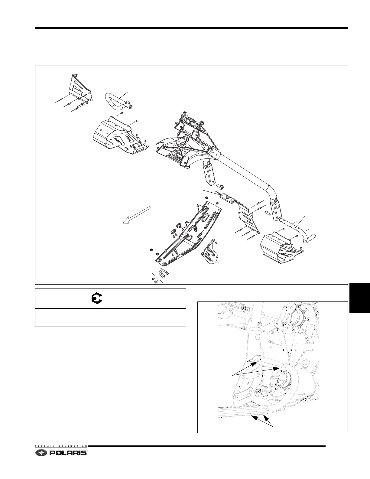
Left/Right Foot Supports - RUSH /
Switchback Models
Assembly Notes:
To remove the rear over structure from the tunnel after all
of
the fasteners are removed, the rivets attaching the
lower footrests to the footrest tubes have to be removed
along with the rivets attaching the footrest tubes to the
tunnel grippers.
After removing the rear over structure, the rivets securing
th
e upper footrest panels to the tubes can be drilled out.
LH
RH
Front
REAR OVER STRUCTURE
FOOTREST TUBE
FOOTREST TUBE
RH UPPER FOOTREST
RH LOWER FOOTREST
LH LOWER FOOTREST
LH UPPER FOOTREST
CLUTCH GUARD
TPS GUARD
A
A
B
= T
A: 22 ft-lbs (30 Nm)
B: 7.4 ft-lbs (10 Nm)
RIVETS
RIGHT SIDE ASSEMBLY SHOWN
RIVETS

Table of Contents

Questions and Answers:

Question and Answer IconNeed help?

Do you have a question about the Polaris 600 RUSH 2010 and is the answer not in the manual?

Polaris 600 RUSH 2010 Specifications

General IconGeneral
Horsepower120 HP
Engine Displacement599 cc
Cylinders2
CoolingLiquid
Bore x Stroke77.25 mm x 64 mm
Fuel SystemCleanfire Injection
IgnitionDigital CDI
Front SuspensionPRO-RIDE
Rear SuspensionPRO-RIDE
Track Width15 in
Track Lug Height1.25 in
Front Travel9 in
Ski Stance42.5 in
BrakeHydraulic Disc
Width48 in
StarterElectric
Drive ClutchP-85
Track Length121 in
Rear Travel14 in
Ski TypeGripper
Driven ClutchTEAM

Related product manuals