7.32
Shocks
FOX™ PS-5 ASSEMBLY
1. Thoroughly clean all of the components with solvent
and allow to air dry. Discard all used wear bands and
o-rings.
NOTE: The PS-5 rebuild kit (PN: 1500611) will supply
a
ll of the required o-rings, wear bands and a u-cup
seal.
Lubricate all components with new shock oil prior to
as
sembly.
2. Thoroughly clean the FIST scraper, bearing
ass
embly, and piston assembly with solvent. Dry with
compressed air. If compressed air is not available, dry
parts using clean, lint free paper towels and let sit in
a well-ventilated area, to allow the remaining solvent
to evaporate.
3. Install the new, well lubricat
ed, o-ring into the FIST
scraper. Check to make sure the seal is properly
seated, and is not twisted. If a tool is required to aid
in proper seating of o-ring, use the non-writing end of
a pen, or a similar soft, blunt object, to push it in.
4. Install new, well lubricated, o-rings into the bearing
h
ousing. Correct placement of the shaft seal o-ring is
in the groove next to the DU bushing. Check to make
sure the seals are properly seated, and are not
twisted. If a tool is required to aid in proper seating of
o-ring, use the non-writing end of a pen, or a similar
soft, blunt object, to push it in.
5. Install the new u-cup seal into bearing. The u-cup seal
sh
ould be installed so the cupped end is facing the DU
bushing inside of bearing. Check to make sure seal is
properly seated. If a tool is required to aid in proper
seating of U-cup seal, use the non-writing end of a
pen, or a similar soft, blunt object, to push it in.
6. Install FIST scraper into housing
. The stepped side of
the FIST scraper should be visible.
7. Using a small pair of snap-ring pliers,
install the snap-
ring into the bearing housing. Check for proper
orientation of the snap ring. The flat side of the snap-
ring should be visible. Check to make sure the snap-
ring is properly seated.
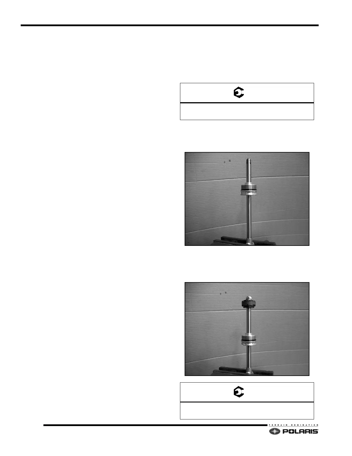
8. Place the shock rod eyelet in a bench vise with the
th
readed end up.
NOTE: If shock rod eyelet was serviced, install eyelet
on shoc
k rod and torque to specification. Use shock
rod holding tool (2871352) to secure rod.
9. Install shock rod seal protector onto shock rod
(2
201639). Lubricate the shock rod with shock oil.
10. Install the bearing assembly onto the shock shaft.
11. Remove the shock rod seal protector. Install the
piston valve assemb
ly onto the shock rod.
12. Install washer and new lock nut. Torque lock nut to
s
pecification.
Shock Body Eyelet
50 ft-lbs (68 Nm)
Piston Valve Lock Nut
18 ft-lbs (24 Nm)

 Loading...


