3.13
Engine/Cooling/Exhaust
3
Crankshaft Index
Polaris crankshafts are pressed together. The connecting
rod journal center lines are indexed 180° apart from each
other.
It is sometimes necessary to chec
k multi-cylinder
crankshafts to verify that one cylinder has not been forced
out of position relative to the other cylinder. Some causes
for a “out of index” crankshaft include but are not limited to
the following:
• Hydrolock from water or fuel
• Impact to drive clutch from object or accident
• Abrupt piston or other mechanical failure
• Engine lock-up due to drive belt failure
Symptoms of an out of index crankshaft can include but
are not
limited to the following:
• Unexplained piston failure on one cylinder (i.e.
se
vere detonation, broken ring lands, etc.)
• Excessive vibration of engine, back-firing, etc.
• Rough idle, poor top speed.
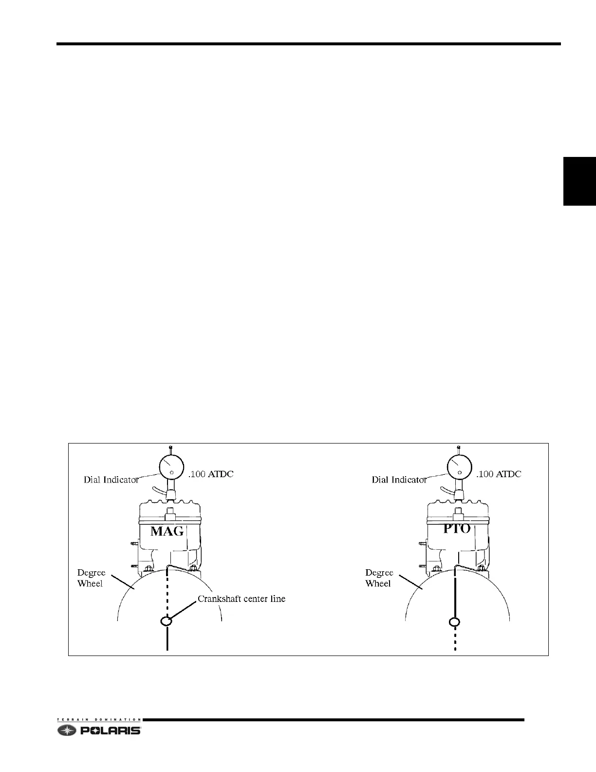
Checking Crankshaft Index
1. Remove the drive belt and drive clutch.
2. Securely fasten a large degree wheel on the flywheel
or
PTO end of the crankshaft. Make sure that it is
mounted concentrically with the crankshaft center
line.
3. With a section of wire (wire coat hanger), anchor it to
a
convenient spot. Bend one end at the outer
perimeter of the degree wheel as shown below.
4. Install a dial indicator into the magneto end cylinder
sp
ark plug hole. The ignition timing is referenced by
the magneto end.
5. Locate TDC as accurately as possible by finding the
ce
nter of the point where there is no piston movement
note the “Zero” the dial indicator at this point.
6. Continue to rotate the crankshaft in the normal
d
irection of rotation until the dial indicator reads .100"
(2.54mm) after top dead center (ATDC).
7. Bend the pointer or move the degree wheel until the
p
ointer aligns with a 180° mark on the degree wheel.
8. With the pointer aligned, make sure the degree wheel
and
pointer are secured and will not move out of
position. Re-check accuracy of this location a few
times. The pointer should align with the 180° mark
when the dial indicator reads .100” (2.54mm) ATDC.
NOTE: Do not move the crankshaft, degree wheel or
p
ointer after the initial setting on the MAG end
cylinder - simply read the wheel and dial indicator.
9. Remove the dial indicator and install in PTO cy
linder.
Repeat finding TDC process. Note the degree wheel
indication when the dial indicator reads .100" ATDC.
It should be 180° (+/-2°) from the MAG cylinder mark.
 Loading...