7.34
Shocks
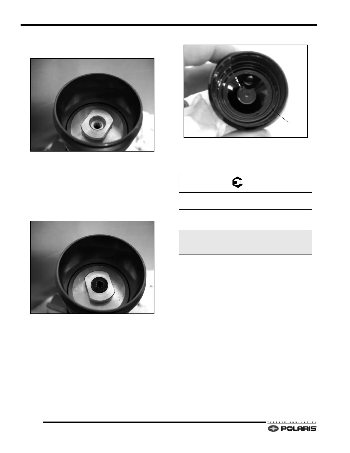
23. Install the IFP without the bleed screw into the shock
body. Set the IFP depth to the specifications noted at
beginning of this chapter.
NOTE: Keep enough shock oil on top of the IFP to
p
revent air from getting in under the IFP.
24. Stroke the shock rod several times as before to purge
a
ny trapped air under the IFP.
25. After all of the air has been removed and the IFP
l
ocation is verified, push the shock rod back into the
shock, and install the bleed screw and o-ring.
26. Pour out any residual shock oil above the IFP into a
su
itable container, but note the tube doesn’t need to
be completely cleaned of shock oil.
27. Install a new o-ring into the body cap.
28. Apply Red thread lock to the first two threads of the
bod
y cap. Do not allow thread lock to come into
contact with the o-ring. Install the body cap onto the
shock body and torque to specification.
29. Set the nitrogen pressure on the fill
tank valves to
specification.
30. Install the gas fill tool into the charge port
and insert
the fill needle. Charge the shock. Hold the fill tool in
place for at least 30 seconds.
31. During this time, the sho
ck rod must fully extend.
32. After charging the shock, in
spect the body to verify
there are no leaks. Compress the shock rod several
times to verify function and that air is not present in
the shock oil.
PS-5 Body Cap
75 ft-lbs (101 Nm)
Nitrogen Pressure
200 psi (1379 kPa)

 Loading...


