Slide Scanner Repair Manual Diagnostics and Troubleshooting
151
Dark Uniformity Response (Fourier)
Part three of the test checks for fixed frequency sources of noise in the dark response.
Fixed frequency sources tend to create highly objectionable artifacts such as streaks and
diagonal lines. Typical sources of fixed frequency noise are the power supply switching
circuit, the lamp inverter, and certain clock and digital signals. High fixed frequency
responses tend to occur when there is a problem with grounding or the power supply
shield.The test performs a fourier analysis on the dark response, relative to the fixed
pattern dark response calculated above. It reports which frequency had the largest
response, relative to the fixed pattern dark response calculated above. It reports which
frequency had the largest response, the Max peak fixed freq, and checks that the size of
the response at that frequency is less than the limit in power units. Typical peak
responses are less than 50 for the SS35 Plus. The Part Number 1E6536A controller PC
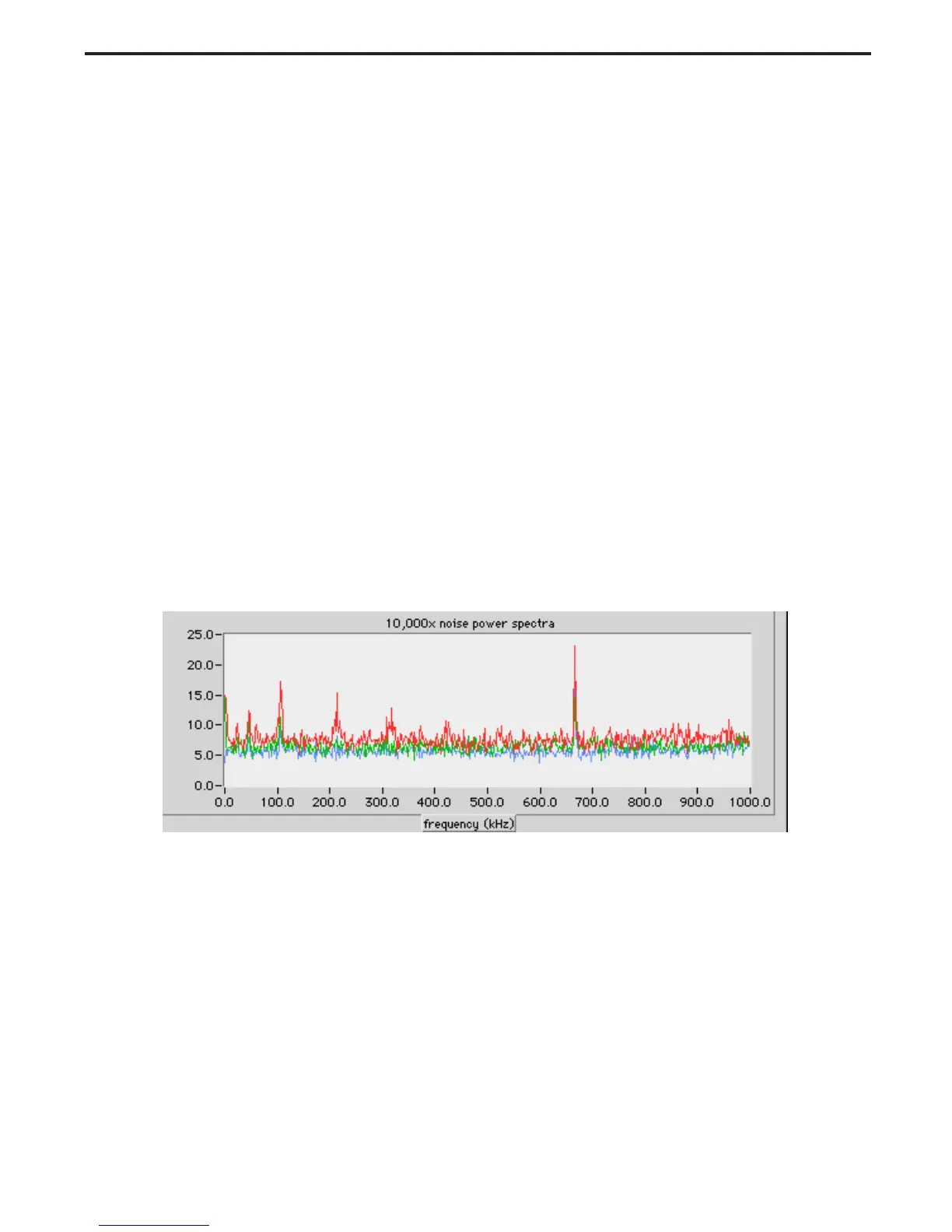
board in the SS35ES typically exhibits a peak of a few thousand at 667 kHz.
The source of the 667 kHz noise shown in Figure 5-17 is in the controller PC board layout
itself, and does not occur in the older P/N 1F4512 version of the controller PC board.
Large peaks at 0 kHz indicate a slow drift from line to line, and are usually associated with
warm-up problems. Frequencies of ~25 kHz and multiples thereof are typically sourced
from the lamp inverter. Harmonics of ~100 kHz are typically sourced from the power
supply. Failure at the latter frequencies is usually associated with bad grounding of the
power supply shield.
Figure 5-17. Noise power spectrum of fixed dark response (see figure 5-15)
 Loading...