Slide Scanner Repair Manual Functional Description
33
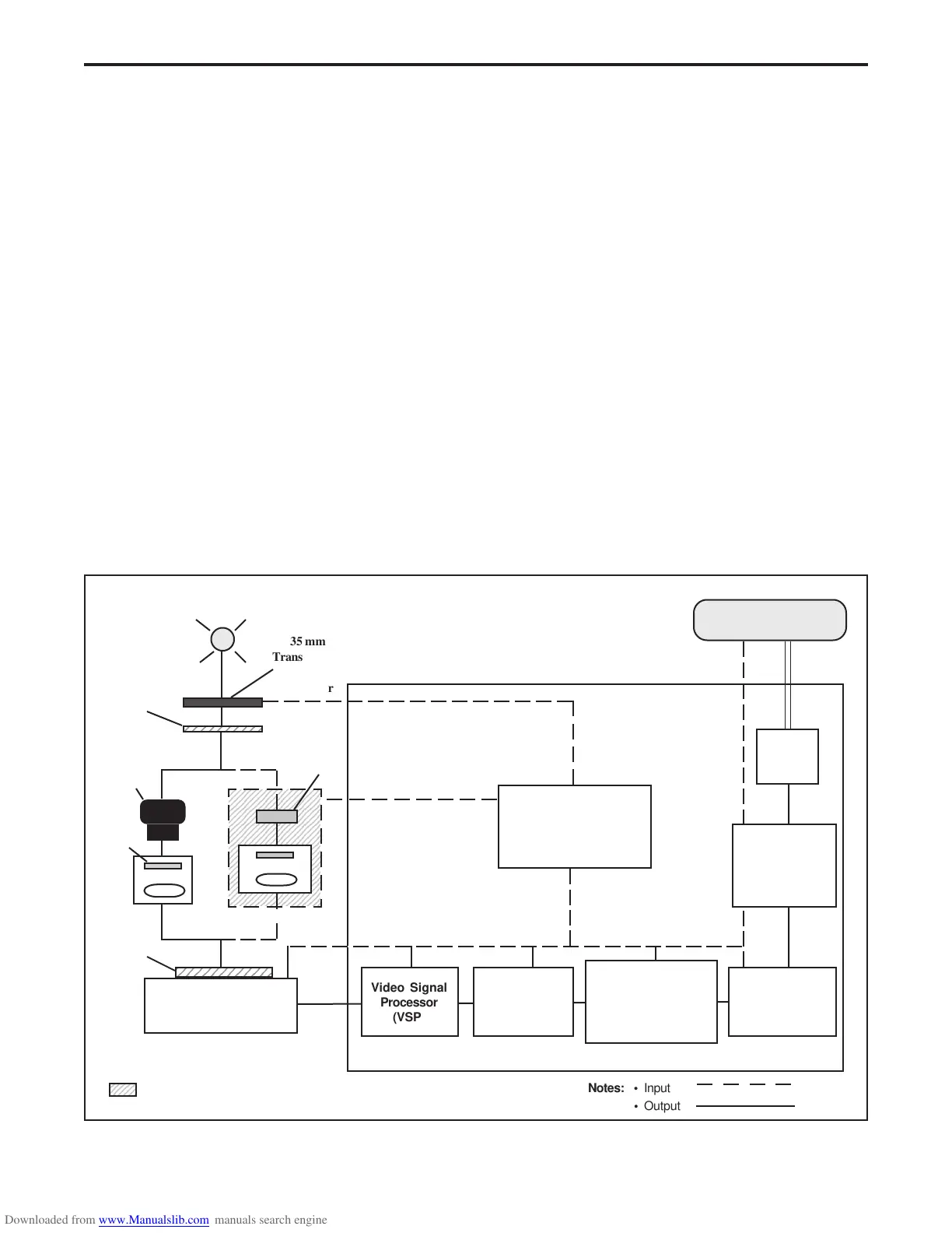
Scanner Process Overview
Upon command from the host computer, a scan operation is initiated. When this scan operation
is initiated, the microcontroller on the main controller PC board coordinates all the slide scanner's
electronic systems in digitizing, color-correcting and sharpening the image, then transmitting it to
the host's memory (Figure 2-1). The microcontroller sets scanning mode and area of interest
according to commands received from the host computer before the scan starts.
The transporter system carries the image through the scanning area (slot) while the lamp
illumination and optics projects and focuses the image line-by-line onto the CCD array on the
image sensor PC board. The image sensor circuits generate analog electrical signals
proportional to the intensity of the light. The output of the CCD array is then buffered and
multiplexed into the video signal processor (VSP) where it is processed and then fed into the
analog-to-digital (A/D) converter. The analog-to-digital (A/D) converter (10-bit A/D converter
for SS35/SS35 ES, 12-bit A/D converter for SS35 PLUS) converts the analog signal into a
digital image. Next, the primary correction ASIC applies correction parameters for uniformity to
the digital image. The primary correction ASIC then sends uniformity corrected image data to
the preview image buffer. When the host computer requests the image data, the preview image
buffer applies it through the secondary color correction ASIC pipeline where the user/film file
color correction, tone scale correction and sharpness parameters are applied. The corrected
image data is then sent to the host computer via the SCSI interface.
Figure 2-1. Scanning process
35 mm
Transparency
1234567890123
1234567890123
Transporter
Video Signal
Processor
(VSP)
A/D
Converter
SCSI
Interface
Color
Correction
ASIC
(ESCAPADE)
Main Controller
PC Board
Image Sensor
PC Board
Microcontroller
Lamp
Host Computer
Scanning
Area
8-Bit
Bus
Primary Correction
ASIC for SS35/SS35 ES
or
DSP for SS35 PLUS
Preview
Image
Buffer
Filter Wheel
CCD
Lens
ND/IR/AR
Filter
Opaque/ ND
Filter
Tunnel
- Filter Set Assembly w/Stepper Motor used on original SprintScan 35. Also used on
SprintScan 35 ES up to serial no. B6xxxxxxD.
2345
23456789012345678
23456789012345678
23456789012345678
23456789012345678
23456789012345678
23456789012345678
23456789012345678
23456789012345678
23456789012345678
23456789012345678
23456789012345678
23456789012345678
23456789012345678
23456789012345678
23456789012345678
23456789012345678
23456789012345678
23456789012345678
23456789012345678
23456789012345678
23456789012345678
Lens
AR/IR Filter
SS35
SS35 ES
SS35 PLUS
Notes: • Input
• Output
 Loading...