69
Slide Scanner Repair Manual Calibration and Adjustments
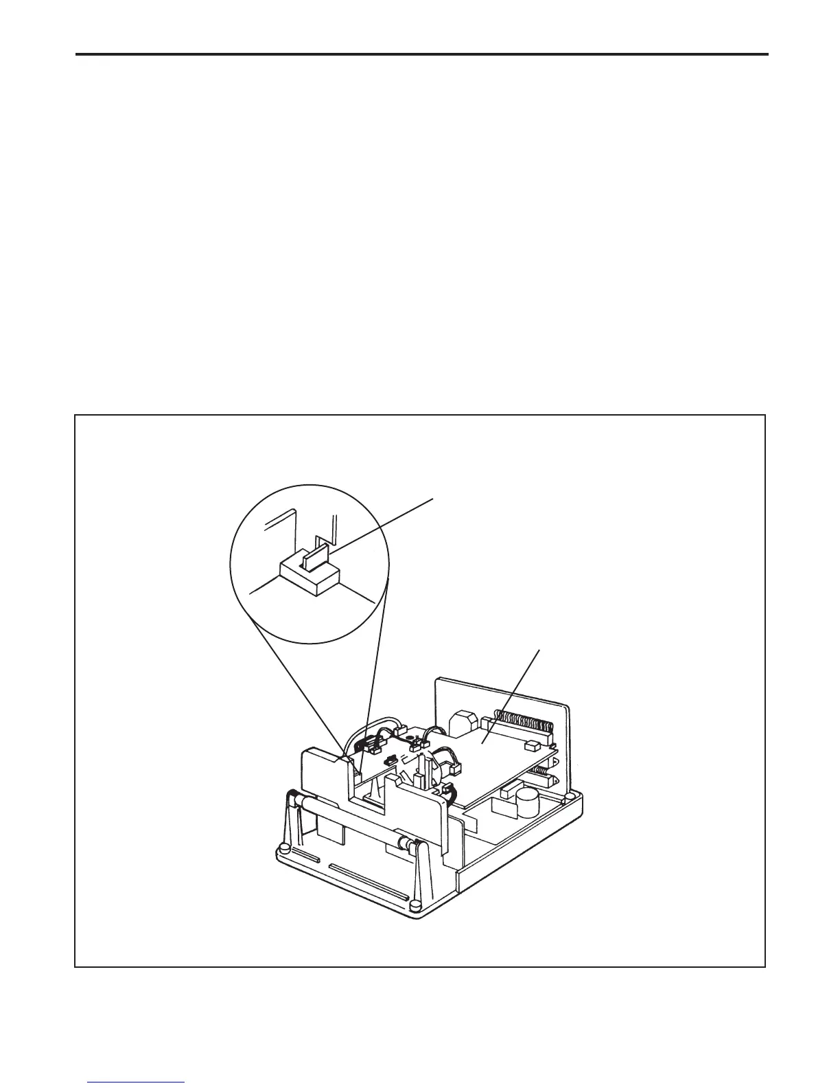
Transporter Photo-Sensor Tab Alignment
Note: This alignment procedure must be performed each time the main controller board is
removed during disassembly or when it is replaced.
1. Manually rotate the lead screw of the chassis assembly until the transporter photo-sensor tab is
properly centered inside the middle of the transporter's photo-sensor (U1) on the main controller
PC board (Figure 3-15) .
2. If the transporter photo-sensor tab is not properly centered, loosen the screws that secures the
main controller PC board to thechassis and back plate assemblies and then slightly
reposition the main controller PC board until the transporter photo-sensor tab is properly
centered inside the middle of the transporter's photo-sensor .
3. Tighten the screw that secures the main controller PC board to the chassis and back plate
assemblies. (SS35/SS35 ES only)
Figure 3-15. Transporter photo-sensor tab alignment
U1
Main Controller
PC Board
Transporter
Photo-Sensor Tab
 Loading...