59
Slide Scanner Repair Manual Calibration and Adjustments
Adjustments
Power Supply
Note: The +15 Vdc and -15 Vdc voltages are dependent on the load that is being drawn
on the +5 Vdc line. To make sure that the operating voltage are properly set, the
+5 Vdc power supply voltage must be adjusted to +5.0 +/- 0.1 Vdc.
1. Setup the voltmeter (Fluke #8026B or equivalent) as follows:
• On/Off Switch - ON
• AC/DC Mode - DC
• Volt/A Range - 10 V Full Scale
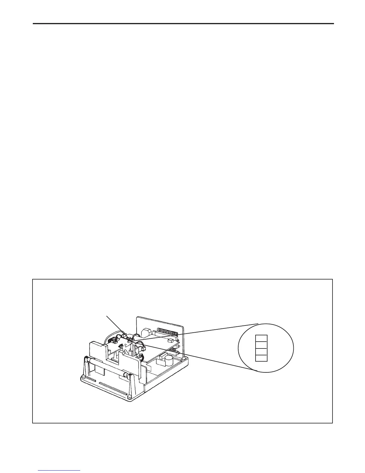
2. Connect the voltmeter to pin 1 of connector J6 on the main controller PC board (Figure 3-4).
The voltmeter should read +5.0 +/- 0.1 Vdc.
3. If the voltage reading at pin 1 of connector J6 is incorrect, adjust as follows:
• Insert a plastic tweaking tool into the voltage adjustment access hole (Figure 3-4) on the
main controller PC board.
• Adjust potentiometer R60 on the power supply PC board until the voltmeter reads the correct voltage
• Remove the plastic tweaking tool.
4. Disconnect the voltmeter from pin 1 of connector J6 on the main controller PC board.
Figure 3-4. Power supply voltage adjustment
Voltage Adjustment
Access Hole
Connector
J6
1
2
3
4
+5V
GND
+15V
-15V
 Loading...