42
Slide Scanner Repair Manual Functional Description
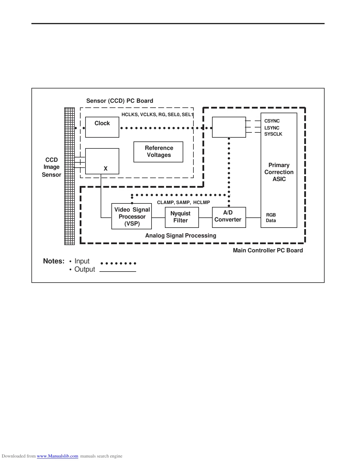
Image Sensor PC Board
The image sensor PC board consists of a CCD image sensor and its associated analog signal
processing support circuitry. Refer to simplified block diagram (Figure 2-5) and the image sensor
PC board schematics in Section 6 of this Repair Manual when reading the description of the image
sensor PC board.
Figure 2-5. Image Sensor PC board
CCD Image Sensor
The CCD image sensor is Polaroid's custom 4000 element tri-linear (RGB) time-delay
integration device. It has built in dark reference pixels and independently addressable
horizontal clocks. Lines of red, green, and blue image data are acquired simultaneously and
clocked out sequentially in an order determined by the specified application. The lines of
color are offset spatially by an integral number of lines.
Light from the lamp passes through the slide onto the surface of the CCD image sensor,
which generates electrical signals proportional to the intensity of the light. The CCD image
sensor functions so that the magnitude of the electrical signal is linearly proportional to the
intensity of received light. Since the CCD image sensor scans one line at a time, a stepper
motor is used to move the slide so the CCD image sensor can scan the entire slide.
Timing
○○○○○○○○○○○○○○○○○○○○○
CSYNC
LSYNC
SYSCLK
○○○ ○○○○○○○○○○○○○○○○○
2345
2345
2345
2345
2345
2345
2345
2345
2345
2345
2345
2345
2345
2345
2345
2345
2345
2345
2345
2345
2345
2345
2345
2345
2345
2345
2345
2345
2345
2345
2345
2345
2345
2345
2345
2345
2345
2345
2345
2345
2345
2345
2345
2345
2345
2345
2345
2345
2345
2345
2345
2345
2345
2345
2345
2345
2345
2345
2345
2345
2345
○○
Clock
Drivers
Buffer
&
MPX
CCD
Image
Sensor
A/D
Converter
Video Signal
Processor
(VSP)
Nyquist
Filter
○○
○○○○○○○○○○○○○○○
CLAMP, SAMP, HCLMP
Reference
Voltages
Primary
Correction
ASIC
RGB
Data
Sensor (CCD) PC Board
Notes: • Input
• Output
Main Controller PC Board
Analog Signal Processing
○○○○○○○○
HCLKS, VCLKS, RG, SEL0, SEL1
 Loading...