79
Slide Scanner Repair Manual Parts Replacement
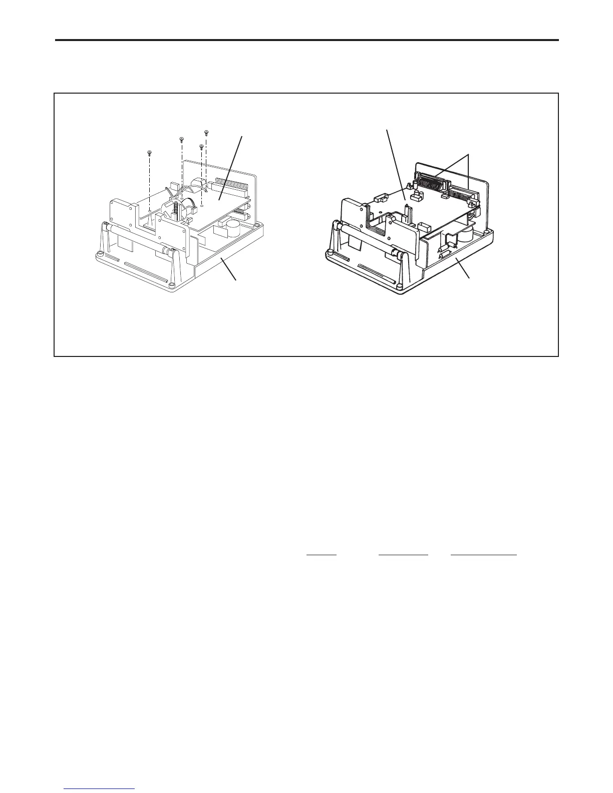
3. Remove all screws securing the main controller PC board to the bottom case (Figure 4-6).
For the SS35 PLUS, remove the four (4) fasteners securing the two (2) SCSI connectors
Figure 4-6. Removing main controller PC board
Installation
1. Install the main controller PC board.
2. Install and tighten all screws that secures the main controller PC board to the bottom case.
3. Connect all electrical connectors/cables to the main controller PC board.
Electrical cables to be reconnected:
SS35 SS35 ES SS35 PLUS
• Transporter Stepper Motor Cable J1 J1 J1
• Filter Wheel Stepper Motor Cable J4 N/A N/A
• Power Supply Cables J5 & J6 J5 & J6 J5 & J6
• CCD Sensor Ribbon Cable J3 J3 J3
• Fan Assembly Cable J9 J9 J8
• SCSI Interface Ribbon Cable J10 J10 N/A
• SCSI Select Switch Cable N/A N/A J14
• SCSI Bus Terminator ON/OFF Switch N/A N/A J13
4. Install the top housing.
Main Controller
PC Board
Bottom Case
SS35/SS35 ES
SS35 PLUS
Main Controller
PC Board
Bottom Case
SCSI
Connectors
 Loading...