Slide Scanner Repair Manual Functional Description
41
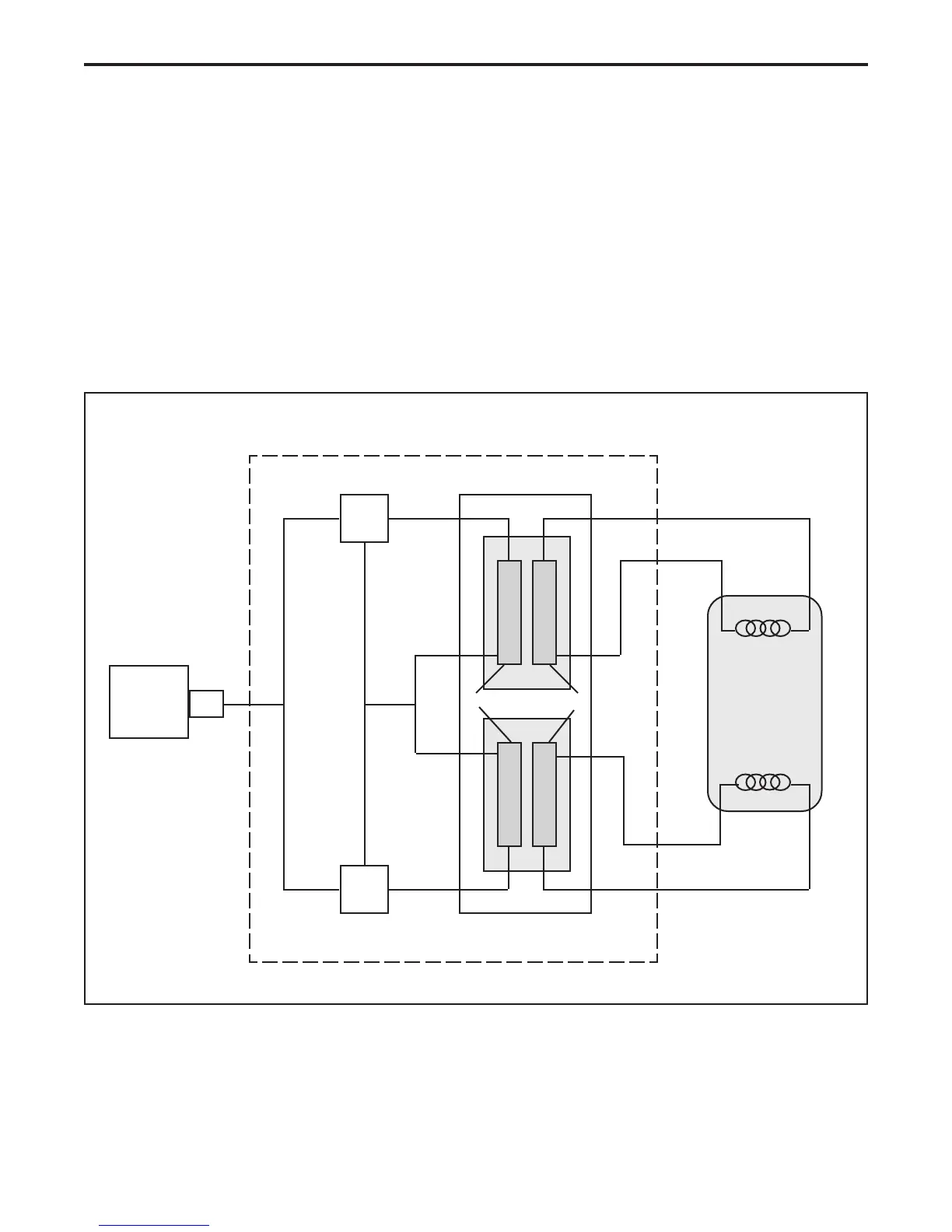
AC Inverter PC Board
The AC inverter PC board generates the necessary AC voltage to power the slide scanner's
lamp. It consists of a switching inverter network (Q1 and Q2), a transformer (T1), and a lamp.
Refer to simplified block diagram (Figure 2-4) and the AC inverter PC board schematic in
Section 6 of this Repair Manual when reading the description of the AC inverter PC board.
When the slide scanner's Power ON/Off (1/0) switch is set to its ON (1) position, + 5 Vdc is
applied through connector J1 on the power supply PC board to the input of the switching network
(Q1 and Q2) on the AC inverter PC board. The switching network generates an oscillating + 5
Vac voltage that is applied to the primary of transformer T1. The secondary output of transformer
T1 generates: cold start voltage of 238 V RMS and operating voltage of + 21 V RMS. The
fluorescent lamp turns on and stays on until the slide scanner is turned off.
Figure 2-4. AC inverter PC board
Q 1
AC Inverter PC Board
Q 2
Power Supply
PC Board
J 1
T 1
Orange
Red
White
+ 5 Vdc
Blue
Lamp
Lamp
+ 21 V rms
+ 21 V rms
Primary Secondary
 Loading...