Slide Scanner Repair Manual Diagnostics and Troubleshooting
153
non-uniformity for each of the three RGB sensors. These profiles are tested to find potential
borderline calibration problems which might cause problems in the field once the lamp ages
slightly or is replaced. Pixels flagged as “bad pixels” in the normal calibration are ignored in
the uniformity analysis. The uniformity tests also ignore roughly 100 pixels on either end of the
field.
Uncorrected Light Uniformity Test
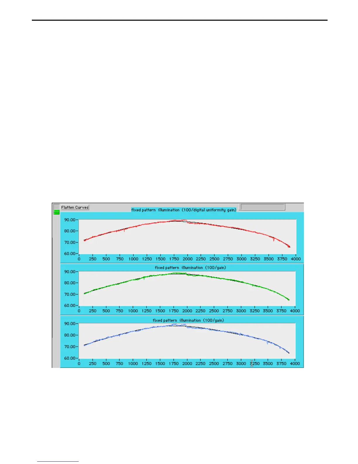
The light portion of the test is based on the gain uniformity profile of the slide scanner. The
light signals to the CCD is typically lower at the edges than in the center, due to non-uniformity
in the lamp as well as the cosine 4 field losses of the lens. Both of these factors tend to vary
slowly across the field, causing predominant slow curves seen in Figure 5-19. These gross
variations are tracked using a polynomial curve fit function, which is drawn in black in the
three plots shown. Smaller and sharper perturbations, which are not tracked by the curve fit,
are caused by the non-uniformity in the CCD’s response, and by dust or dirt in the CCD’s
cover glass or the lamp. Three parameters are tested in this portion of the test: Fine
uniformity, Gross Uniformity, and Illumination.
Figure 5-19. Uncorrected light uniformity profile 100/gain vs. pixel number
 Loading...