78
Slide Scanner Repair Manual Parts Replacement
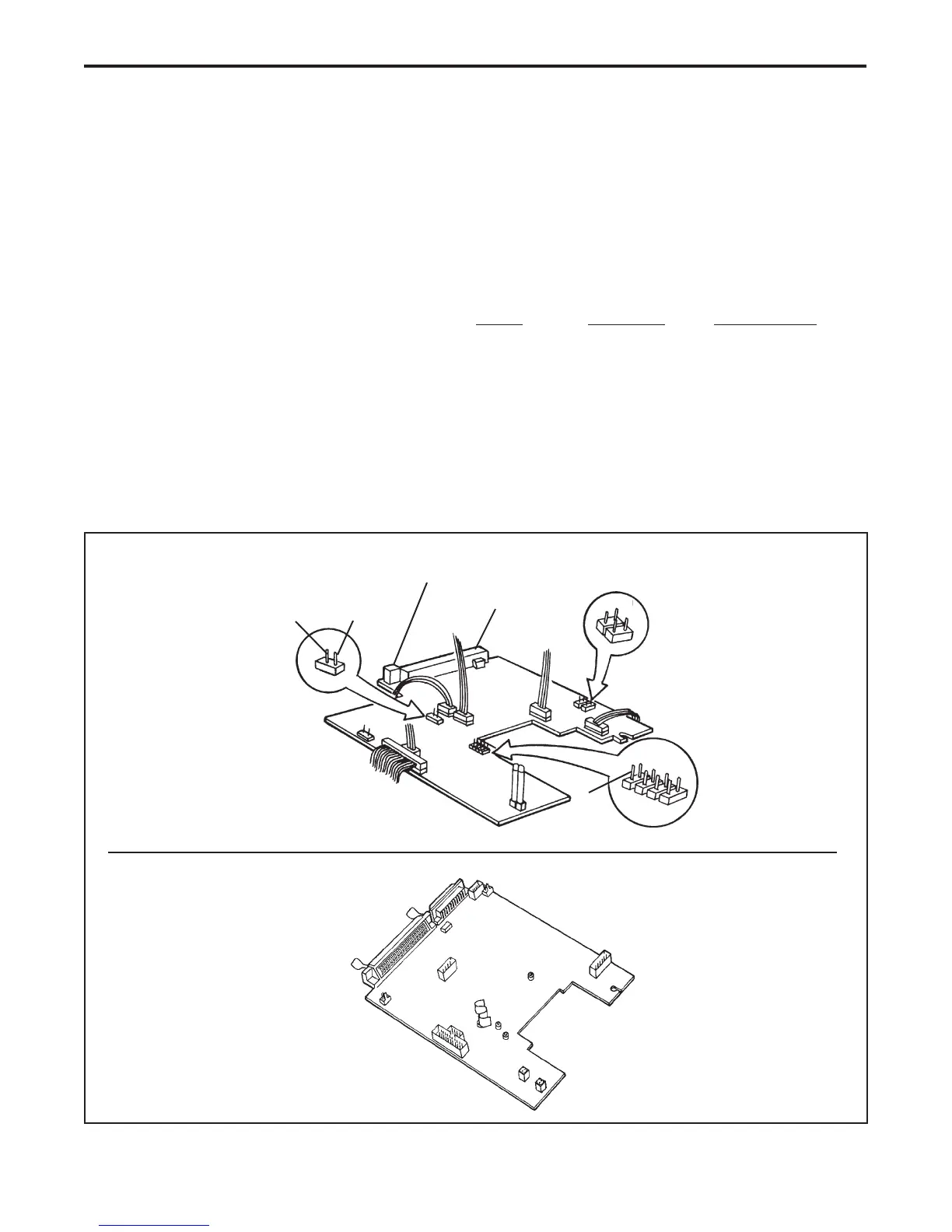
Main Controller PC Board
Removal
1. Remove the top housing.
2. Disconnect all electrical connectors/cables from the main controller PC board. Lift out the main
controller PC board (Figure 4-5).
Electrical cables to be disconnected:
SS35 SS35 ES SS35 PLUS
• Transporter Stepper Motor Cable J1 J1 J1
• Filter Wheel Stepper Motor Cable J4 N/A N/A
• Power Supply Cables J5 & J6 J5 & J6 J5 & J6
• CCD Sensor Ribbon Cable J3 J3 J3
• Fan Assembly Cable J9 J9 J8
• SCSI Interface Ribbon Cable J10 J10 N/A
• SCSI Select Switch Cable N/A N/A J14
• SCSI Bus Terminator ON/OFF Switch N/A N/A J13
Figure 4-5. Main controller PC board
SS35/SS35 ES
SS35 PLUS
GND
LSYNC
1
2
Video
Out
5
8
6
Not Used
J 1
J 2
J 3
J 5
J 8
J 4
J 6
J 9
J 10
1
3
7
(GND's - Pins 1, 3, 5, 7)
4
2
J 7
SCSI Interface
SCSI Select Switch
J10
J12
J14
J13
J8
J6
J5
SCSI
Fuse
LYSNC
J3
AGND
J1
ADIN
 Loading...