190
Chapter 5 Section I: Replacement Procedures
Installation
CAUTION
To prevent electrostatic damage to electronic components, always wear
a properly grounded static wrist strap when you handle memory
modules and circuit boards.
NOTE: Flash SIMMs from one controller board must be placed in the same
slot on a replacement controller board. Installing flash memory from
one controller board to another does not transfer all operating system
software, so you must download the emulation again.
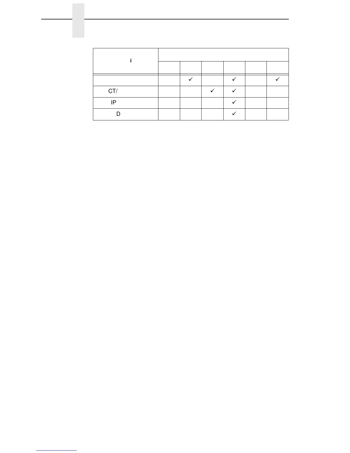
1. Observing the correct pin orientation, install the new security module, if
required by the emulation. (See the chart on page 189 and Figure 26 on
page 191.)
2. Insert the memory module into the correct socket on the controller board:
a. Position the SIMM with the notched end toward the right side of the
controller board. (See Figure 26, page 191.)
b. Press the SIMM into the socket with the top of the SIMM angled away
from the center of the board. When the SIMM is seated in the socket,
gently push on the ends until it locks in the upright position.
3. Cabinet Models: Install the paper path (page 199).
Pedestal Models: Install the top cover assembly (page 179).
4. Download the emulation (page 150).
5. Return the printer to normal operation (page 133).
6. Using the configuration printout(s) you made in step 1 of the removal
procedure, reset and save the printer configuration(s). (Refer to the
User’s Manual.)
CT/VGL/LP+
CT/IPDS/LP+
CT/IPDS/PGL/LP+
CT/IPDS/VGL/LP+
Emulation
Security Module Number
123456