Memory And Security Modules
191
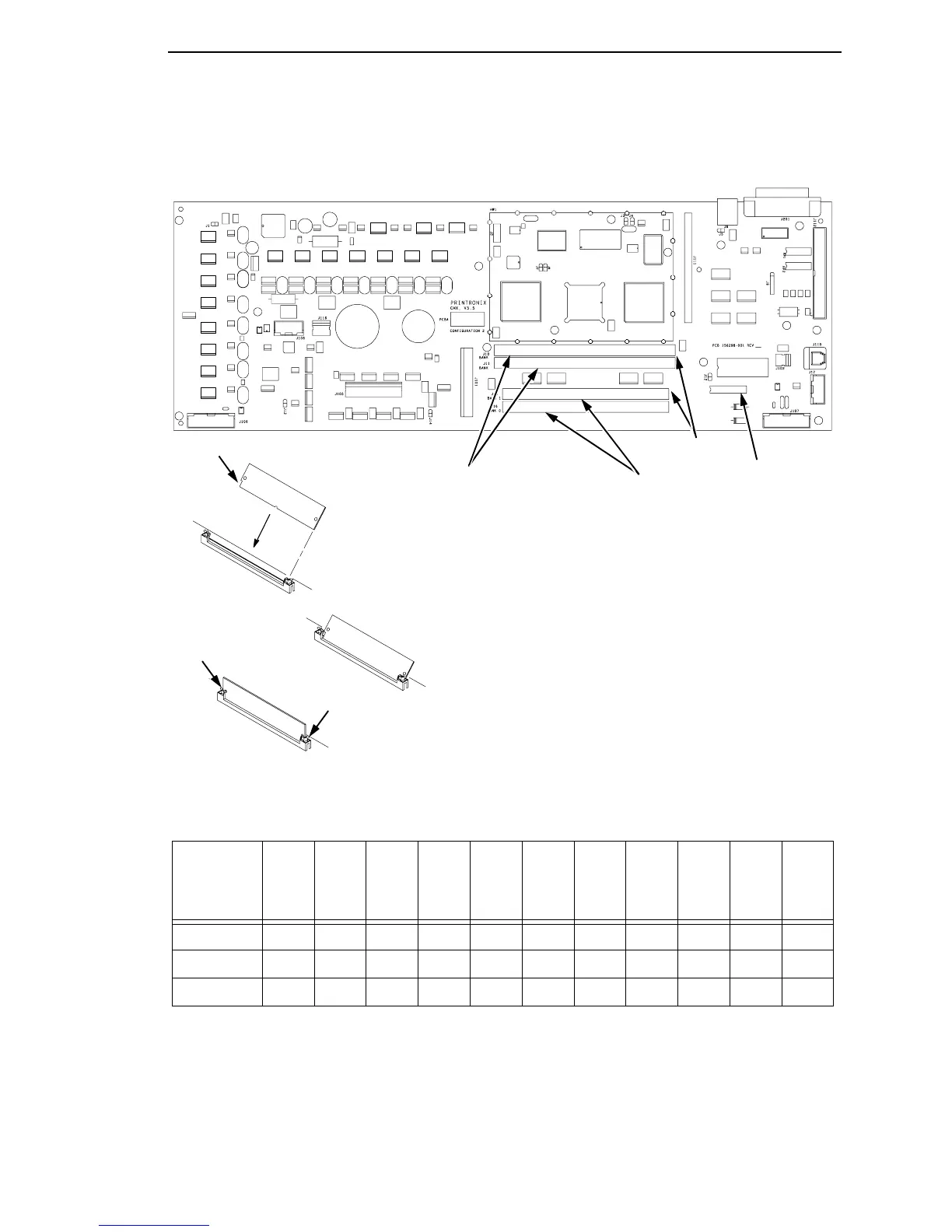
Figure 26. Memory and Security Modules
2
1
3
Bank 0
Bank 1
Bank 0
Bank 1
80-pin SIMM
J11 = Bank 0 (must always
be filled)
J10 = Bank 1
Reserved for upgrades
If 1 Flash SIMM, use Bank 0.
If 2 Flash SIMMs, use both
banks but put pre-programmed
SIMMs in J11.
72-pin SIMM
J16 = Bank 0 (must always
be filled)
J15 = Bank 1
Reserved for upgrades
If 1 DRAM SIMM, use Bank 0.
If 2 DRAM SIMMs, use both
banks. (It does not matter which
SIMM goes into which bank.)
IMPORTANT:
No matter what combination of SIMMs is used,
J11 and J16 must always be filled. The controller
board does not support EDO RAM.
Controller Board
Security Module
Notched End
DRAM:
Flash:
Emulation
Options
LP+
IGP
LP+
ANSI
LP+
PGL
ANSI
LP+
VGL
ANSI
LP+
CT
LP+
CT
PGL
LP+
CT
VGL
LP+
IPDS
CT
LP+
IPDS
CT
PGL
LP+
IPDS
CT
VGL
LP+
Flash 4 MB 4 MB 4 MB 4 MB 4 MB 4 MB 4 MB 4 MB 4 MB 4 MB 4 MB
DRAM 4 MB 4 MB 4 MB 4 MB 4 MB 4 MB 4 MB 4 MB 4 MB 4 MB 4 MB
CT Installed No No No No No Yes Yes Yes Yes Yes Yes
Notch
Latch
Latch
Memory Requirements for Emulation Options