347
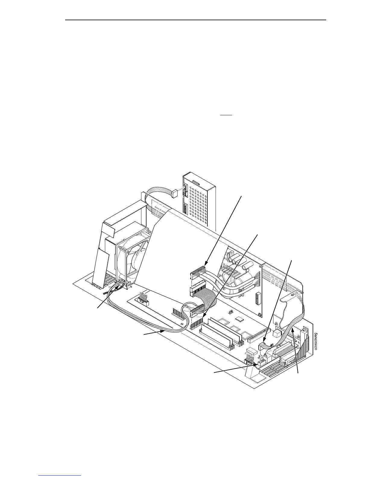
5. Connect the power stacker logic cable P103 to connector J17 or J117 on
the controller board. (Figure 72.)
6. Disconnect the power supply cable from connector J101 on the controller
board. (Figure 72.)
7. Connect power supply cable connector P101 to the stacker power cable,
then connect the stacker power cable to connector J101 on the controller
board. (Figure 72.)
8. Route the stacker power cable in front
of the controller board and down
through the cutout under the card cage fan. (Figure 72.)
9. Route the stacker logic cable through the opening between the card cage
and the cabinet frame and behind the card cage. (Figure 72.)
Figure 72. Stacker Power and Logic Connections on the Controller Board
7
Power Supply Connector P101
Connector J101
Connector P103
CMX Connector J17
CFX Connector J117
Stacker Logic
Cable
Stacker Power Cable
Cutout Beneath
Card Cage Fan