Instrument Functions
R&S
®
NRP2
118User Manual 1173.9157.02 ─ 03
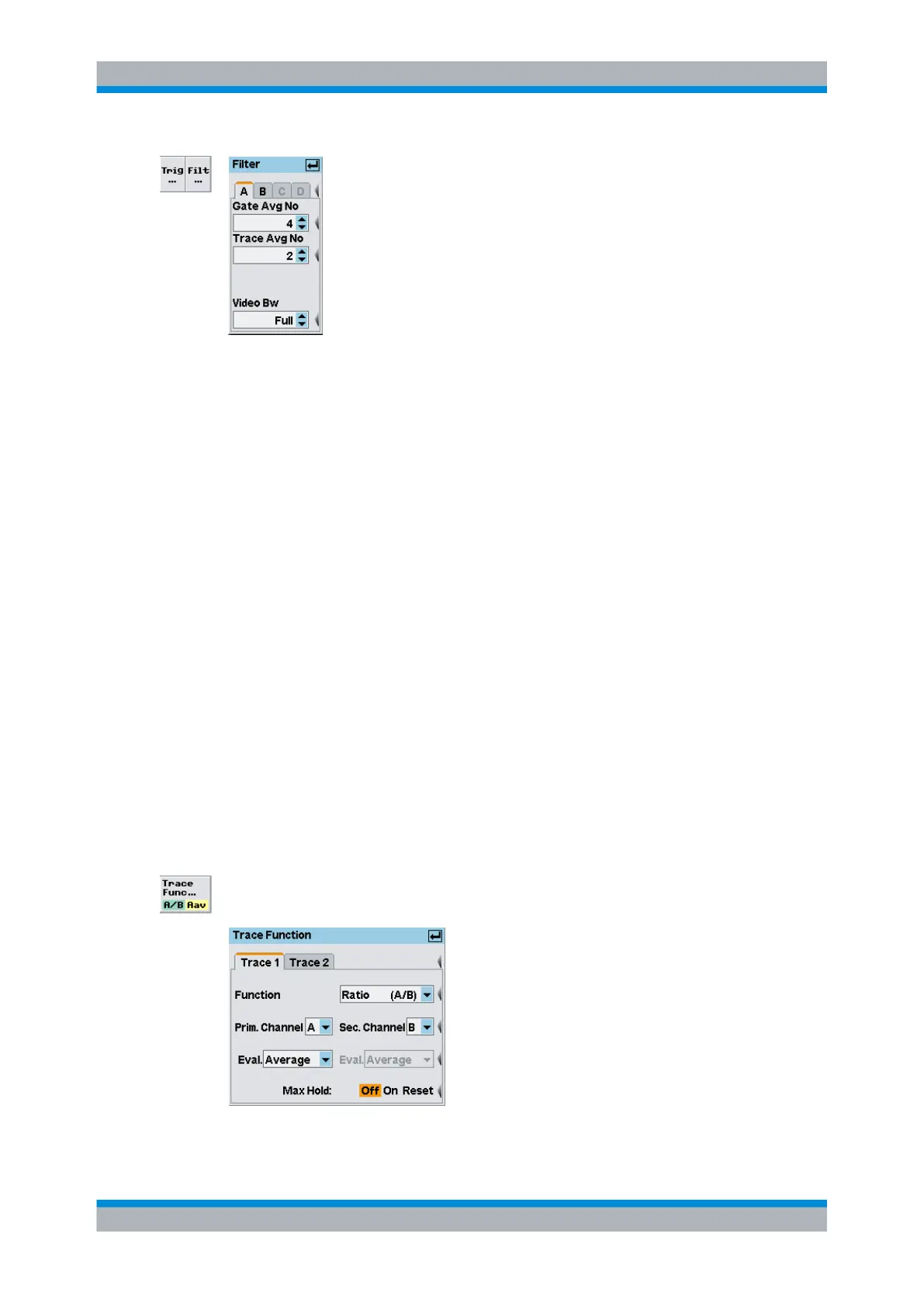
Fig. 4-48: Filter dialog box in Trace display mode
A | B | C | D
Tabs for selecting the sensor.
Note: In remote-control commands, select the sensor with the suffix in command
SENSe<[1]..4>:..., i.e. choose suffix 1 for channel A, channel 2 for B, and so on.
Gate Avg No
Selects the averaging number for averaging the gated measurement results.
Trace Avg No
Selects the averaging number for averaging the traces.
SCPI command:
[SENSe<[1]..4>]:TRACe:AVERage:COUNt on page 282
Video BW
Selects the video filter bandwidth. This setting is available in the R&S NRP-Z8x wideband
power sensors, otherwise it is fixed.
Available values are "Full", "5 MHz", "1.5 MHz", and "300 kHz".
SCPI command:
[SENSe<[1]..4>]:BANDwidth:VIDeo on page 265
4.5.3.4 Trace function settings
The trace function settings are performed in the Window→Graph→"Dis-
play"→"Trace"→"Trace Function" dialog box ("Trace&Statistics" sensor mode).
Fig. 4-49: Trace function
Displaying traces