MODULAR SAFETY INTEGRATED CONTROLLER MOSAIC
8540780 • 10/07/2020 • Rev.38 107
OBJECT FUNCTION BLOCKS
OUTPUT OBJECTS
OSSD (safety outputs)
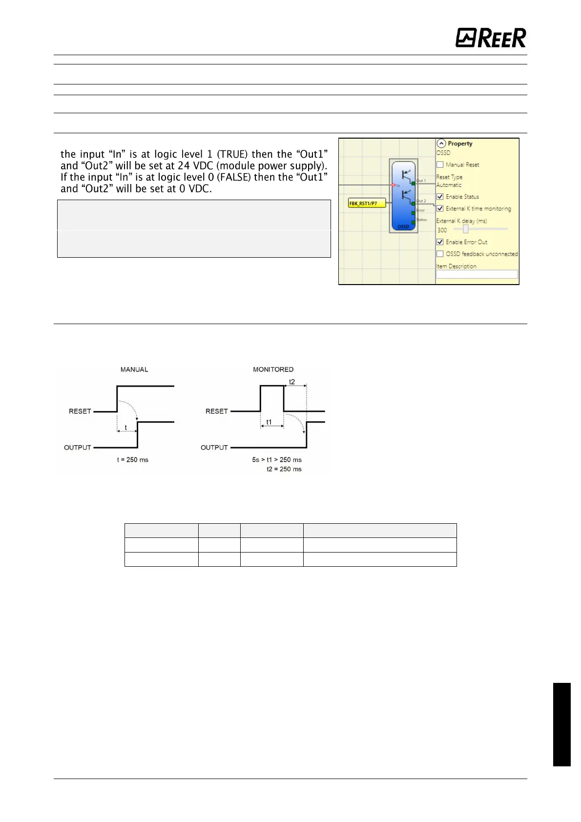
OSSD safety outputs use semiconductor technology, if
Each pair of OSSD outputs has a relative
RESTART_FBK input. This input must always be
connected as indicated in the RESTART_FBK
paragraph.
Parameters
Manual Reset: If selected this enables the request to reset each time the input signal falls. Otherwise,
output Follows directly In input Signal level.
There are two types of reset: Manual
and Monitored. In selecting the Manual
option only signal transition from 0 to 1
is verified. If the Monitored option is
selected, the double transition from 0 to
1 and back to 0 is verified.
Enable Status: If selected, enables the
connection of the current OSSD state to
any point on the schematic.
External K time monitoring: If selected, enables the setting of the time window within which the
external feedback signal is to be monitored (according to following output conditions).
With high level (TRUE) OUTPUT, the FBK signal must be at low level (FALSE) within the set time.
Otherwise, OUTPUT is set to low level (FALSE) and the error is indicated on the master M1 by the
flashing CLEAR LED corresponding to the OSSD in error.
If not selected, the following checks are performed:
1) During power on, the system verifies that the FBK signal is connected to 24 VDC.
2) During normal operation, the system verifies that 24 Vdc are available via the series of NC contacts
of K1/K2.
The FBK signal must meet the following conditions:
1) 24 VDC during power on.
2) 24 VDC within 10 s of the TRUE/FALSE transition of the OSSD outputs.
If one of these conditions are not met, the system detects an error that can only be reset by a power
cycle. This is signaled by a flashing of the CLEAR LED corresponding to the affected output.
When the NC contacts of K1/K2 are not connected, connect the FBK input to 24 VDC.

 Loading...


