EasyManuals Logo

Reer MOSAIC MI8O4C Installation And Use

Reer MOSAIC MI8O4C
239 pages
To Next Page IconTo Next Page
To Previous Page IconTo Previous Page
Page #20 background imageLoading...
Page #20 background image
MODULAR SAFETY INTEGRATED CONTROLLER MOSAIC
20 8540780 • 10/07/2020 • Rev.38
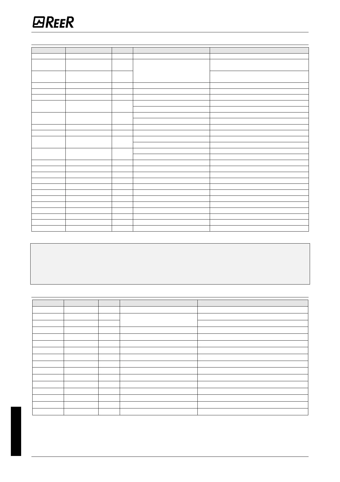
English
Module MI8O4
TERMINAL
SIGNAL
TYPE
DESCRIPTION
OPERATION
1
24VDC
-
24VDC power supply
-
2
NODE_SEL0
-
Node selection
Input ("type B" according to EN 61131-
2 )
3
NODE_SEL1
-
Input ("type B" according to EN 61131-
2 )
4
0VDC
-
0VDC power supply
-
5
OSSD1
Output
Solid State Safety Output 1
PNP active high
6
OSSD2
Output
Solid State Safety Output 2
PNP active high
7
RESTART_FBK1/
STATUS1
Input/
Output
Feedback/Restart 1
Input according to EN 61131-2
SIL 1/PL c output
PNP active high
8
RESTART_FBK2/
STATUS2
Input/
Output
Feedback/Restart 2
Input according to EN 61131-2
SIL 1/PL c output
PNP active high
9
OSSD3
Output
Solid State Safety Output 3
PNP active high
10
OSSD4
Output
Solid State Safety Output 4
PNP active high
11
RESTART_FBK3/
STATUS3
Input/
Output
Feedback/Restart 3
Input according to EN 61131-2
SIL 1/PL c output
PNP active high
12
RESTART_FBK4/
STATUS4
Input/
Output
Feedback/Restart 4
Input according to EN 61131-2
SIL 1/PL c output
PNP active high
13
OUT_TEST1
Output
Short circuit detection output
PNP active high
14
OUT_TEST2
Output
Short circuit detection output
PNP active high
15
OUT_TEST3
Output
Short circuit detection output
PNP active high
16
OUT_TEST4
Output
Short circuit detection output
PNP active high
17
INPUT1
Input
Digital input 1
Input according to EN 61131-2
18
INPUT2
Input
Digital input 2
Input according to EN 61131-2
19
INPUT3
Input
Digital input 3
Input according to EN 61131-2
20
INPUT4
Input
Digital input 4
Input according to EN 61131-2
21
INPUT5
Input
Digital input 5
Input according to EN 61131-2
22
INPUT6
Input
Digital input 6
Input according to EN 61131-2
23
INPUT7
Input
Digital input 7
Input according to EN 61131-2
24
INPUT8
Input
Digital input 8
Input according to EN 61131-2
Table 5

The STATUS SIL 1/PL c outputs are shared with the feedback/restart inputs of the
OSSDs. To use them, the corresponding OSSD must be used with automatic reset
without external feedback monitoring. For example, to use the STATUS1 output
(Terminal 7), you must program OSSD1 with automatic reset without K feedback
monitoring.
Module MI8
TERMINAL
SIGNAL
TYPE
DESCRIPTION
OPERATION
1
24VDC
-
24VDC power supply
-
2
NODE_SEL0
Input
Node selection
Input ("type B" according to EN 61131-2 )
3
NODE_SEL1
Input
Input ("type B" according to EN 61131-2 )
4
0VDC
-
0VDC power supply
-
5
INPUT1
Input
Digital input 1
Input according to EN 61131-2
6
INPUT2
Input
Digital input 2
Input according to EN 61131-2
7
INPUT3
Input
Digital input 3
Input according to EN 61131-2
8
INPUT4
Input
Digital input 4
Input according to EN 61131-2
9
OUT_TEST1
Output
Short circuit detection output
PNP active high
10
OUT_TEST2
Output
Short circuit detection output
PNP active high
11
OUT_TEST3
Output
Short circuit detection output
PNP active high
12
OUT_TEST4
Output
Short circuit detection output
PNP active high
13
INPUT5
Input
Digital input 5
Input according to EN 61131-2
14
INPUT6
Input
Digital input 6
Input according to EN 61131-2
15
INPUT7
Input
Digital input 7
Input according to EN 61131-2
16
INPUT8
Input
Digital input 8
Input according to EN 61131-2
Table 6

Table of Contents

Other manuals for Reer MOSAIC MI8O4C

Questions and Answers:

Question and Answer IconNeed help?

Do you have a question about the Reer MOSAIC MI8O4C and is the answer not in the manual?

Reer MOSAIC MI8O4C Specifications

General IconGeneral
BrandReer
ModelMOSAIC MI8O4C
CategoryController
LanguageEnglish

Related product manuals