MODULAR SAFETY INTEGRATED CONTROLLER MOSAIC
182 8540780 • 10/07/2020 • Rev.38
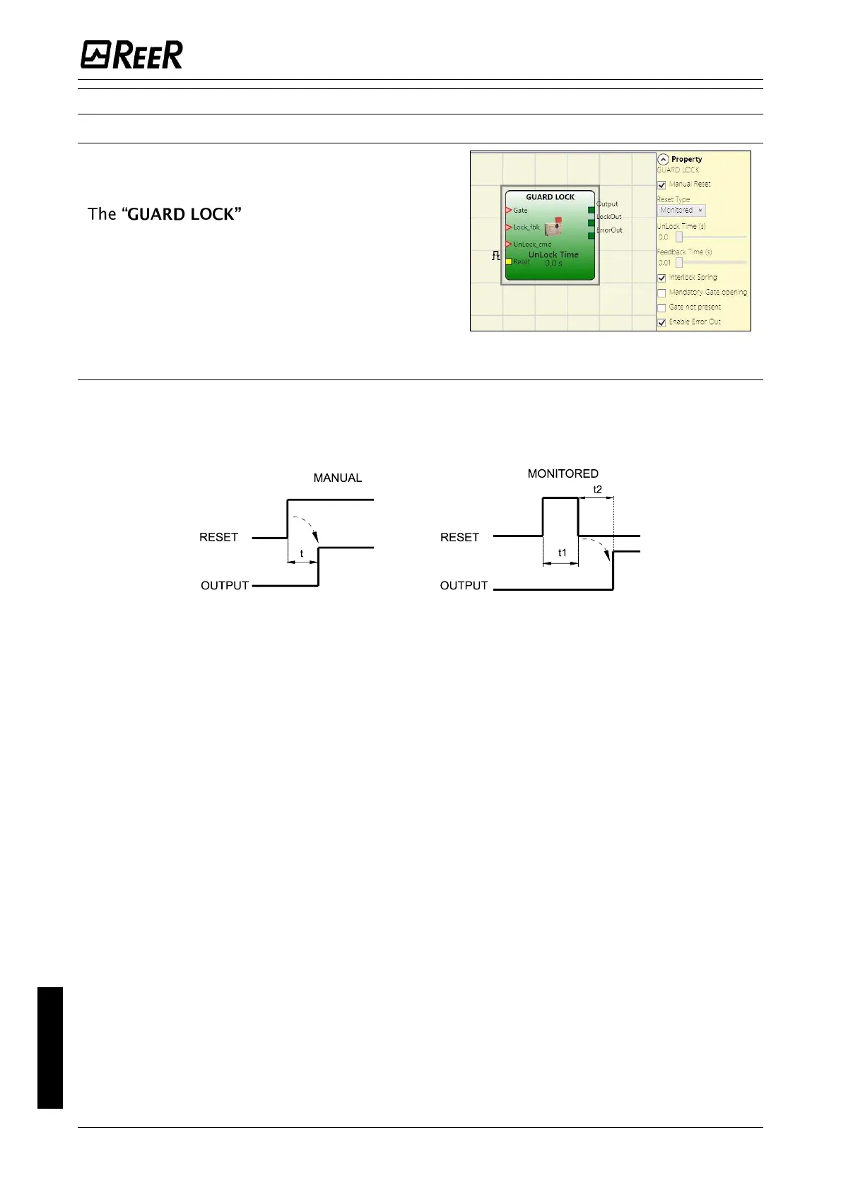
GUARD LOCK OPERATORS (max number = 4 with M1, 8 with M1S)
GUARD LOCK
operator is designed to
control locking/unlocking of an
ELECTROMECHANICAL GUARD LOCK in a
variety of operating contexts.
Parameters
Manual Reset:
There are two types of reset: Manual and Monitored. When Manual is selected the system
only verifies the signal's transition from 0 to 1. If Monitored is selected the double transition
from 0 to 1 and then back to 0 is verified.
5sec > t1 > 250 ms
t2 = 250 ms
Unlock Time (s):
The time that must pass between the UnLock_cmd input reaching and the real guard unlock
(Lockout output).
- 0ms ÷ 1 s Step 100 ms
- 1.5 s ÷ 10 s Step 0.5 s
- 15 s ÷ 25 s Step 5 s
Feedback Time (s):
Maximum delay accepted between LockOut output and Lock_fbk input (must be the one shown on
the lock data sheet with appropriate gap decided by the operator).
- 10ms ÷ 100 s Step 10 ms
- 150ms ÷ 1 s Step 50 ms
- 1.5 s ÷ 3 s Step 0.5 s
Interlock Spring: The guard is locked passively and released actively, i.e. the mechanical force of
the spring keeps it locked. The guard thus continues to be locked even when the power supply is
disconnected.
Mandatory gate opening: Only with door opening and subsequent confirmation of input GATE, the
cycle proceeds.
Gate not present: If selected, enables configuration without Gate but only with LOCK FEEDBACK
(feedback coil lock).
Enable error out: This can be selected to enable a signal (Error Out) to indicate a lock malfunction.
When Error Out = 1 (TRUE) there is a fault in the lock. (e.g. open door with guard lock locked,
Feedback Time exceeding the maximum allowed, etc.).

 Loading...


